
| C R G | CRG Reports | Exterior | Engine | 1967 Model ID |
| Numbers Decode | General Info | Interior | Transmission | 1968 Model ID |
| Drivetrain Decode | Options | Underhood | Chassis | 1969 Model ID |
CRG Research Report - © 2000-2023, Camaro Research Group
First-Generation Camaro Lock Systems
Author -|
Reviewed by the CRG Last Edit: 05-Feb-2023 Previous Edit: 09-Apr-2009 Original Release: 19-Mar-2000 |
|
|
Briggs & Stratton (B&S), the lock division of which has since become Strattec (www.strattec.com), has been the primary supplier of locks (and key blanks for these locks) to General Motors essentially since the beginnings of GM. Briggs & Stratton was formed early in the 20th century by two former students of North Dakota State University, Steve Briggs and Harold Stratton. Together the two men started a business supplying parts to the relatively new automotive/truck industry. At one point, they bought a motorized AO Smith buckboard and from this developed and built two Briggs & Stratton automobiles.
Automotive design and assembly proved to be a temporary diversion. Briggs and Stratton decided to supply the industry rather than compete in it, and focused on developing, manufacturing, and supplying automotive hardware. From handles, hinges, and latches, B&S branched out into locks and keys, and to support these, developed high-volume die-casting technology and related processes. (This same experience and technology was later applied to the now better-known small-engine business.) B&S quickly became the exclusive supplier of GM locking systems. However, a particularly difficult labor strike at B&S in the late 1940s created costly disruptions at GM assembly plants. To minimize the impact of a recurrence, GM obtained a licensing agreement from B&S to allow Rochester Products, better known as the fuel delivery systems branch of GM, to build B&S locking systems as a second source.
Keys were manufactured separately from the locks, in advance. The blanks were stamped, their grooves milled, the lettering on the key bow coined, and the key bittings cut per code in a punching operation. The keys were stored in bulk by letter designation and code, and then added to the locksets prior to packaging. Basic locksmith terminology of the physical features of keys is illustrated in the schematic below:

|
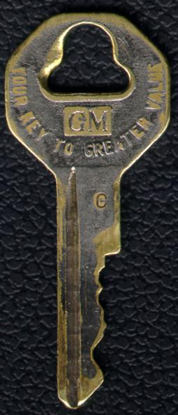
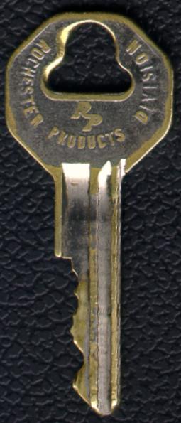
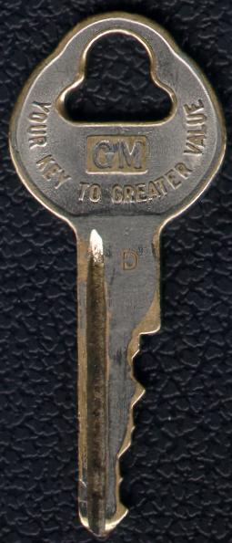
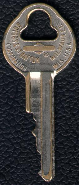
From 1935 to 1966 GM used a single keying system with only one key blank design, B&S groove style 15. Many models prior to 1967 used only one key with an octagonal key bow. If there was a secondary key, it used the same key blade with a different cut and a teardrop-shaped key bow. A new key system with multiple key groove styles was implemented starting with the 1967 model year, brought about by pressure from the U.S. federal government as well as public pressure from growing problems with vehicle theft. GM had planned to implement the new keying system using a new "corporate" key blank displaying the new GM logo and Mark of Excellence slogan, but a decision was made to implement the locking system before the federal deadline, and so the keys from the first two years of the new system (1967-68) used the previous key blank style that noted the manufacturer of origin on the back of the bow (RP or B&S). With the new corporate key design, the indicator of manufacturer origin on the key bow would disappear. To distinguish the manufacturer of origin for service issues, the groove letter that was stamped on the key blade was stamped in different orientations for each of the suppliers. More on this below.
The new B&S keying system used a series of eight key blanks with different blade cross-sectional geometries (key sections). Each blank had a particular key part number and groove type, but were more simply designated by the letters A, B, C, D, E, H, J, and K. The short designation caused the keys in this system to be commonly called the "letter keys". In addition to increasing the number of key sections, the new system added a fifth key cut depth, and so increased the number of key combinations possible on a given key blank by approximately 25% from the earlier system. Both features improved security by making it a little more difficult to interchange keys.
| Lock Key Code | 67-68 Key Comparison | ||
|
|
| Secondary Side 1 |
Secondary Side 2 |
|
 |
 |
As shipped from the GM assembly plant, vehicle keys had a knockout area at the key ring hole that was imprinted with a 4-character code (number/letter/number/number) that correlates to the lock tumbler combination (a 6-digit number described in more detail below). (Only the original keys, and B&S pre-punched factory replacement keys, come stamped with the lock code.) The knockout tabs were made to be removed and stored by the owner in case the keys were lost - a locksmith could make a new key from the code number without having to remove a lock. There was a small hole in the knockout area to accommodate a temporary wire key ring. If the knockouts were left in the key, the tiny hole through the knock-out was often drilled-out to a larger diameter to allow a key ring to pass through the hole. Until about 1980, B&S furnished GM key blanks only with the knockouts intact. Locksmith Dorothy Friend wryly suggests that this must have been "to give the locksmith something to do during slack periods, since most of us needed the knockouts punched out to get them on the hooks of our key boards." The knockouts for the key blanks, obviously, did not have a code stamped on them.
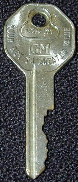
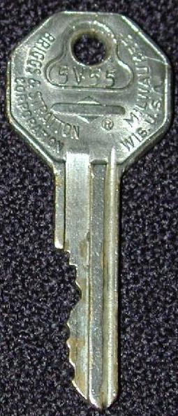
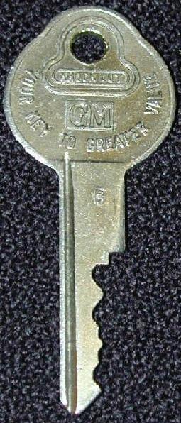
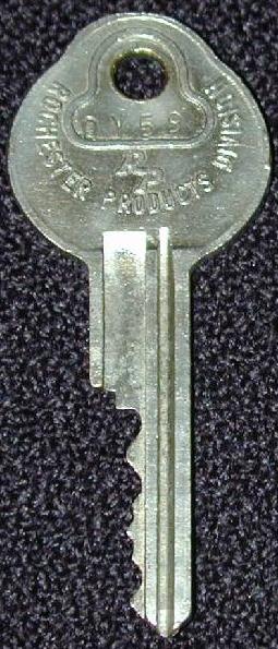
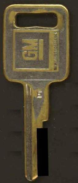
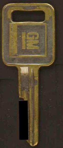
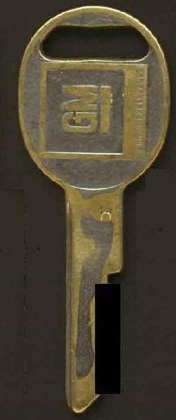
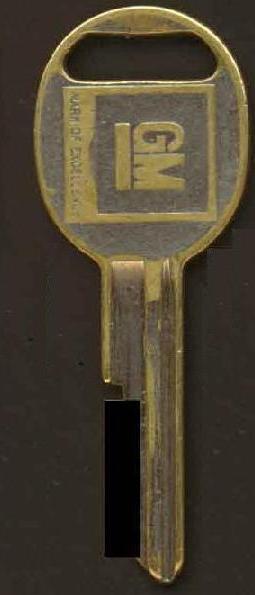
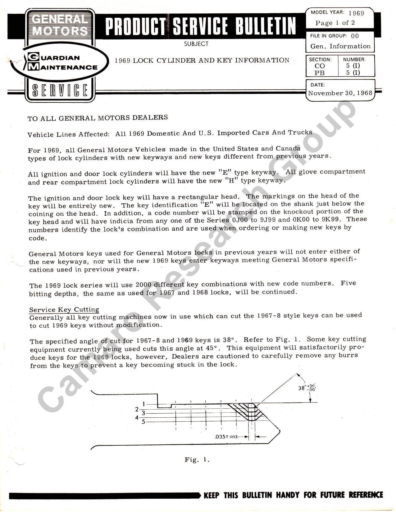
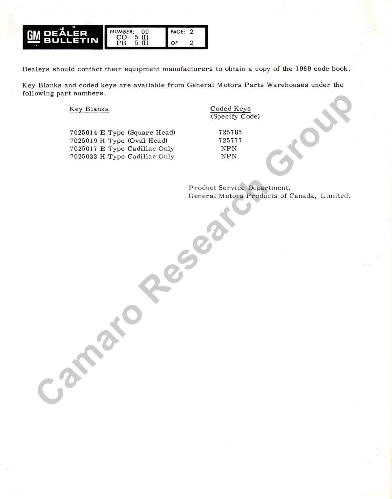
The 1967-68 years were a transition period that saw the earlier-style (1935-66) key bows (the "bow", in locksmith terms, is the head of the key that is used as a grip or handle) retained on the new letter-key blades. Several examples of keys are illustrated. The first set (to the right) shows a pre-67 (actually 1936) GM secondary key with the knockout intact (but the knockout hole drilled-out to a larger size). Note that the GM and B&S logos are on the opposite sides compared to later years, as well as the use of the pre-WWII "BASCO" logo (for Briggs And Stratton COrp) and the all-numeric keycode. The 1967 A/B example shows a primary (ignition/door) key from a Briggs & Stratton lockset, while the secondary key is from a Rochester Products lockset. Like the 1936 example, the 1967 set has the knockout wire ring hole drilled out. Also note the relative similarity between the Groove 15 key section and the Groove 50 (A) key section - the difference being that the A key has a wider upper groove. In the 1968 C/D example with the knockouts removed, note that the primary, or ignition/door key, is from a Rochester Products lockset, while the secondary key is from a Briggs & Stratton lockset. The 1969 example, also with the knockouts removed, shows the new key bow shapes - the rectangular and oval forms still in use today, aka, the "Corporate" keys. Note in the 1969 example that there are no distinguishing features of the lockset manufacturer on the Corporate keys. This GM information bulletin p.1 and p.2 provides more information on the new 1969 keys and locks.
| Primary Side 1 |
Primary Side 2 |
Secondary Side 1 |
Secondary Side 2 |
 |
 |
 |
 |
| Primary Side 1 |
Primary Side 2 |
Secondary Side 1 |
Secondary Side 2 |
 |
 |
 |
 |
| Primary Side 1 |
Primary Side 2 |
Secondary Side 1 |
Secondary Side 2 |
 |
 |
 |
 |
To bring us to completely modern times, while GM has since introduced new design locking systems, it has continued to use the letter key system on other models. The first VATS (Vehicle Anti-Theft System) ignition locks were used on the 1986 Corvette. This system used one of the letter key sections, but added a resistor pellet embedded in the neck of the primary key. The primary key also required a longer neck to allow the resistor pellet contacts to reach into the ignition lock. The first year for Camaro to have a VATS ignition was 1989. Other neck length and bow shape changes occurred on other models in subsequent years, but the letter keyways continued to be used.
In 1992 Skylark and Cavalier got a new primary keyway - the first keyway change on a domestic vehicle line since 1967. (Imported vehicles like Allante (87), Nova (86), Sprint (84) and Luv (81) had different keying systems.) Other new keyways have since been introduced, as well as double-bitted keys (keys with cuts on both sides).
The eight "letter key" blanks are actually four pairs, since each vehicle with this locking system uses two different key sections. (The key section is the exact cross-sectional configuration of the key blade region as viewed from the bow toward the tip, as shown in the previous illustration.) One of the four pairs is used in each model year, rotating through the following order: A/B, C/D, E/H and J/K. The first designation from each pair is the primary (or "square-bow" key) used for ignition and door locks (later - only ignition); following this is the designation for the "oval-bow" key used in the secondary locks (trunk and glove box - later also the doors).
The different designations for the key blanks reflect differences (in geometry and location) in the milled grooves that run down the length of the key. Four pairs of grooves in the new system instead of the single groove in the old system allowed additional combinations of keys, which provided additional security. For example, the key cuts can be identical on keys from two different pairs, say an A blank and a C blank, but they physically can't be inserted into the other lock because the milled grooves are in different locations. (Exceptions to this can occur due to extensive wear on both the keys and locks that can allow worn keys of some letters to be inserted into worn locks of other letters. Additionally, there are some non-OEM replacement locks, including some by Strattec, that use a universal keyway and will take any of the B&S blanks, but these were never used on GM vehicles at the assembly plant.) The different milled grooves are shown in the side-by-side comparisons of the ABCDEHJK blanks in the illustration below.
Starting in 1974, the primary key was changed to fit only the ignition and the secondary key was applied to the rest of the locks. As noted several times previously, the actual bow-shape of the 1967-68 letter key blanks differed from later years, with the primary keys having a bow shaped like an incomplete octagon (sometimes called the "hex" key) rather than a rectangle/square, and the secondary keys being tear-drop shaped rather than oval. These 1967-68 key bows were the same as those used in the previous key design from 1935-1966, but the key blades used the different letter key sections.
The letter-key designations are stamped on the keys. According to Len White, Chief of the B&S Automotive Locks Division, during the years when both Rochester and B&S supplied locking systems on identical key blanks (1969 and following), the stamps from the two suppliers were oriented in different directions. Rochester Products (it is believed) stamped their keys so that the letter was correctly oriented when the key is held with the blade horizontal to the ground. The stamp on (B&S) was correctly oriented when the blade was held perpendicular to the ground.
The lock type, letter designation, B&S blank number, B&S groove type and year of application for all GM keys from 1935 to the present (excepting modern non-letter key systems), are shown in the below left table.
Examples of GM key types (but not all possible bow/groove types) are shown below right in the excerpt below from a mid-1980s B&S document. Note the groove number/letter shown to the left of each key blank, and the cross-section shape shown to the right of each key blank.
|
|
The 4-character GM key code (which correlate to the 6-digit tumbler number) was logged by the factory and documented on the broadcast sheets and the documentation provided to the dealer when the new vehicle was delivered. However, the key codes can also be found stamped on many of the locks themselves. On first-generation Camaro they are generally are stamped on the outside of the door and trunk lock cylinder cases, and on the glovebox cylinder plug (which must be removed from lock case to see the stamp - see the removal instructions for 67-68 glovebox locks in the appendix.)
2,000 key codes were assigned for each of the primary and secondary keys in a given year (some out-of-sequence exceptions to the normal selections have been documented). The actual tumbler numbers associated with the key-codes were semi-randomized, documented in tables, and will not be reproduced here. For the first-generation Camaro years, the 12,000 4-character key codes were generally taken from the following list:
               1967          1968          1969
           ------------  ------------  ------------
Primary    0V00 to 9V99  0N00 to 9N99  0J00 to 9J99
           0W00 to 9W99  0P00 to 9P99  0K00 to 9K99

Secondary  0X00 to 9X99  0R00 to 9R99  0L00 to 9L99
           0Y00 to 9Y99  0T00 to 9T99  0M00 to 9M99
|
These locks have 6 tumbler positions (except the glovebox, which fits a 6-position key but only uses 5 of them) and there are 5 possible cut depths for each tumbler. At most there are 5x5x5x5x5x5 combinations, or a total of 15,625 theoretical key cut combinations for each groove type. In actual practice there are far fewer combinations, since some combinations would never be used, such as where all 6 tumblers are at the same height, or tumbler combinations resulted in impossible key geometries, such as where the 1 and 5 tumblers would have been in adjacent positions. As a general rule, there were never more than three of same code in a row and contiguous positions were never more than two apart. This results in 1820 different key codes.
The process of cutting the factory key cuts, "key bitting," used a punching process rather than the more commonly used replacement key process of grinding, such as used in hardware store key duplicators. The factory machine was called, naturally, a "key bitting punch":
key bitting punch, n - a manually operated device which stamps or punches the cuts into the key blade, rather than grinding or milling them.
B&S blade geometry is illustrated in the following figure. The nominal blade height is 0.250 inch. An uncut portion of the blade can count as one of the "cut" positions (a "no-cut" cut), called depth #1 (r1 in the figure). Beyond the uncut position there are 4 additional cut depths that require removal of metal from the key blank. Despite the common term "root depth", or simply "depth", these dimensions are the amount of blade height that remains after the cut, rather than the amount of metal that is removed. (The "bitting depth" is the complement to the "root depth", but we will use only "root depth" in the remainder of this discussion.)
Each standard tumbler size cuts 0.025-inch more from the blade than the previous size: the #2 cut leaves a 0.225-inch high blade, #3 a 0.200-inch blade, #4 a 0.175-inch blade, and with a #5 cut 0.150 inch of the blade remains. So the root depth is the measurement from the back of the blade to the deepest point of the cut. (Note that the 1935-1966 B15 blade used the first four of these five cuts.)
|
|
The next critical dimension is the distance of each cut from the key blade shoulder, also known as the "bow stop". Each of the six tumbler positions is located at a specific nominal dimension from the blade stop as shown in the above Figure. The distance between each tumbler position is 0.092 inch, and this is the same distance that the middle of the key cuts must be from the adjacent tumbler.
By measuring the uncut depth of your key blade with a caliper at each of the appropriate positions, you can reverse-engineer the tumbler depth numbers and determine the tumbler combination of your lock. From this, many locksmiths can do a reverse lookup in a table to arrive at the original factory code that was stamped on the locks and the key knockouts, and printed on broadcast sheets and vehicle assembly plant shipping summaries. When you perform the measurement, wear on the keys will make the cuts deeper (remember - this is actually the distance across the remaining uncut area), so you would generally adjust your measured value upward to the next standard tumbler depth. For example, if a cut measures 0.219 inch, you would adjust up to the #2 tumbler (0.225 inch), rather than down to #3 (0.200 inch). The convention for listing the cuts in the combination for these is from bow to tip - a key with a combination of 132445 would have more of the key blade cut away toward the tip than near the bow. An example of this is shown below:
|
|
The key cut appearance resulting from a factory key punch is somewhat simulated by several hard-to-find aftermarket key punch machines. However, you will have a difficult time distinguishing between the results from one of these punch machines and one of the better rotary grinding machines. The rotary cuts will have a slight arc (the cutters are around 2-1/2 inches in diameter) that is difficult to see on a short cut, and the angle of cut may (or may not) be as close as those produced by the punches. Punch machines include:

|

|

|
The locks came with one of two types of tumblers: conventional disk tumblers, used on the glovebox lock, and sidebar disk tumblers, used on all remaining locks. In the case of the sidebar tumblers, activation by the proper key moved all the tumblers to a height that caused a notch in all the tumblers to line-up with a rib in the spring-loaded sidebar. The sidebar then moved inward a distance equal to the height of the rib, which freed the cylinder plug to rotate in the cylinder case.
With the conventional disk tumblers used in the glovebox, the tumblers themselves are the actual restriction that prevents the cylinder from turning. Activation by the proper key moves all the tumblers out of the way and the cylinder plug can then rotate inside the cylinder case.
|
|
The case caps (the bright-metal exterior trim) on door and trunk locks provide a good indicator as to whether the locks have been field serviced. Factory case caps are crimped on (nice and neatly) all the way around the circumference, holding the dust shutter, dust shutter springs, and cylinder plug in the case. A factory case cap is normally destroyed in removal, and replaced with a service-style case cap. It is possible to very carefully pry off a factory cap, and painstakingly restake it; however, if this has been done, the work will be fairly noticeable on the backside of the case where the cap was restaked. Replacement case caps differ from factory cases, having 4 little tabs, about 3/16-inch wide, spaced equidistantly around the diameter of the cap. A replacement cap can be identified by looking at the back of the face for the 4 tabs. A very sharp eye might be able to detect one on the car, since between the tabs, the replacement cap doesn't wrap around to the back to the back of case.
------------------------------------------------------------------------

|
The 1967 Chassis Service Manual has several pages (0-4 to 0-6) on servicing keys and locks, including figure 20 to the right.
From the B&S Service Manual:
The lock is held in compartment door with screw and retainer cup.Note: Be careful not to drop the bolt, spring or pusher if you remove the lock cylinder from the case.
- Removing Lock Cylinder from Case - Hold bolt down and turn key clockwise until stop. Pull out cylinder.
- Replacing Bolt, Pusher and Spring - Keep cylinder out of case. Replace pusher, bolt and spring in order indicated. End of spring must rest in knob recess. Use a screwdriver to force other end of spring over button on bolt.
- Replacing Lock Cylinder - Hold bolt down. Insert cylinder with cam up. Turn key counterclockwise until stop.
With the glovebox cylinder plug out (B&S refers to it as the glovebox cylinder, but from a locksmithing standpoint, it is a cylinder plug that is in need of the case or housing to be a complete cylinder), you will see 5 tumblers. The tumblers are spring-loaded, so one end of each will extend beyond the diameter of the plug when the key is out of the cylinder; when a correctly cut key is in the cylinder, the ends of the tumblers will be flush with the diameter of the plug, allowing the cylinder to be turned, and the catch to be opened.
The trunk/glovebox key code is stamped on the outside of the cylinder plug.
Some older glovebox replacement cylinders were furnished with extra long tumblers staked in; the locksmith "coded" these by inserting the desired operating key in the plug, placing the plug in a special holding fixture, clamping the fixture in a vise, and filing the protruding tumblers to size.
Turn the cylinder as far counterclockwise as it will go, then insert a suitable tool (a partially unwound paper clip works well) in the poke hole in the face to push in the plunger; continue turning counterclockwise, then pull the cylinder.
Replace the plug in the lock case. Put the 2 small dust cover springs in the intentations (in the face of the plug) designed to receive them, place the dust cover over them, then place the face cap over the assembly. If you have a vise available, you may find it helpful at this point to: hold the assembly together by grasping it with a finger at the back of the lock case, and thumb on the face cap; then insert the key in the cylinder. Drape a shop rag loosely over the vise jaws, so you can put the key bow between the jaws (also between areas of the shop rag), and rest the face cap on the tops of the jaws, holding it down, to keep the parts together as you tighten the vise enough to gently hold the key bow. Use a hammer and a fairly large pin punch (up to about 3/16-inch) to tap each of the 4 tabs on the face cap down, to hold the face cap on the lock case. When the face cap is firmly in place, remove the key, and tap the tabs more, as necessary, to get them neatly down.
|
|


