|
|
| C R G | CRG Reports | Exterior | Engine | 1967 Model ID |
| Numbers Decode | General Info | Interior | Transmission | 1968 Model ID |
| Drivetrain Decode | Options | Underhood | Chassis | 1969 Model ID |
CRG Research Report - © 2003-2024, Camaro Research Group
The First-Generation Camaro Assembly Process
Author - John Hinckley|
Reviewed by the CRG Last Edit: 17-Feb-2024 Previous Edits: 14-Mar-2013, 24-Mar-2009, 11-Feb-2006, 07-Feb-2006, 17-Jan-2005 Original Release: 22-Jan-2004 |
Norwood was a very old plant that was typical of the old standard model for Fisher Body/Chevrolet assembly facilities; the Fisher Body plant and the Chevrolet assembly plant were on the same piece of property, but were operated by two separate GM Divisions. Fisher Body built the body shell from the firewall back, and shipped it through a hole in their common wall to the Chevrolet plant, fully painted and trimmed, including the interior, minus the instrument panel, dash and floor-mounted components, and front carpets. Chevrolet then assembled all the rest of the trim, chassis, and final assembly components, including all the front end sheet metal, and shipped the finished cars to the dealers. Fisher Body had a huge Paint Shop for the body, and Chevrolet had their own separate Paint Shop for all the front end sheet metal. Norwood ran two shifts, and produced 57 cars per hour, or 912 per day, and produced only the Camaro until mid-April, 1969, when the Firebird (previously built at Lordstown) was added to their mix.
|
|
Van Nuys had been a traditional separate Fisher Body/Chevrolet assembly operation for many years, similar to Norwood, but was one of the first Fisher/Chevrolet plants to be consolidated under GMAD (GM Assembly Division) management in 1967-68, replacing the formerly separate Fisher Body and Chevrolet managements with a single GM Division in charge of the entire operation. By 1969, the former Fisher Body Paint Shop had been expanded so it also accommodated the Chevrolet front end sheet metal, and the former Chevrolet Paint Shop was abandoned. Trim Shop operations were also consolidated, with some formerly separate Fisher Body and Chevrolet Trim operations combined on the existing trim lines. Van Nuys also ran two shifts, and produced 35 cars per hour, or 560 per day, but only half of those were Camaros in 1969 - the other half of their schedule was full-size Chevrolet Impala and Caprice models.
Paint Shop: Cleans, phosphates, primes, seals, and topcoats the body shell, including stripes, and sends it on to the Trim Shop.
Trim Shop: Installs wiring, glass and moldings, weatherstrips, door and deck lid hardware, interior and exterior trim, taillights, moldings and emblems, headliner, seats and rear carpets, water tests, and ships the trimmed body to Chevrolet.
Trim Line: Installs VIN plate, dash mat, heater or A/C system, wipers, pedal support, instrument panel, cluster and wiring, steering column, front carpets, console, brake booster, rear bumper and guards, and the rear shocks and fuel tank; at Norwood, the body continues to the Final Line for Body Drop, Van Nuys also installs the complete front sheet metal assembly and sends the body to the Final Line for Towveyor chassis-to-body marriage.
Engine Line: Receives engines and transmissions from six different supplier plants and joins them, stamps VIN derivatives, fully dresses and wires/plumbs the engine, engine and trans oil fill, and sends the completed assembly to the Chassis Line.
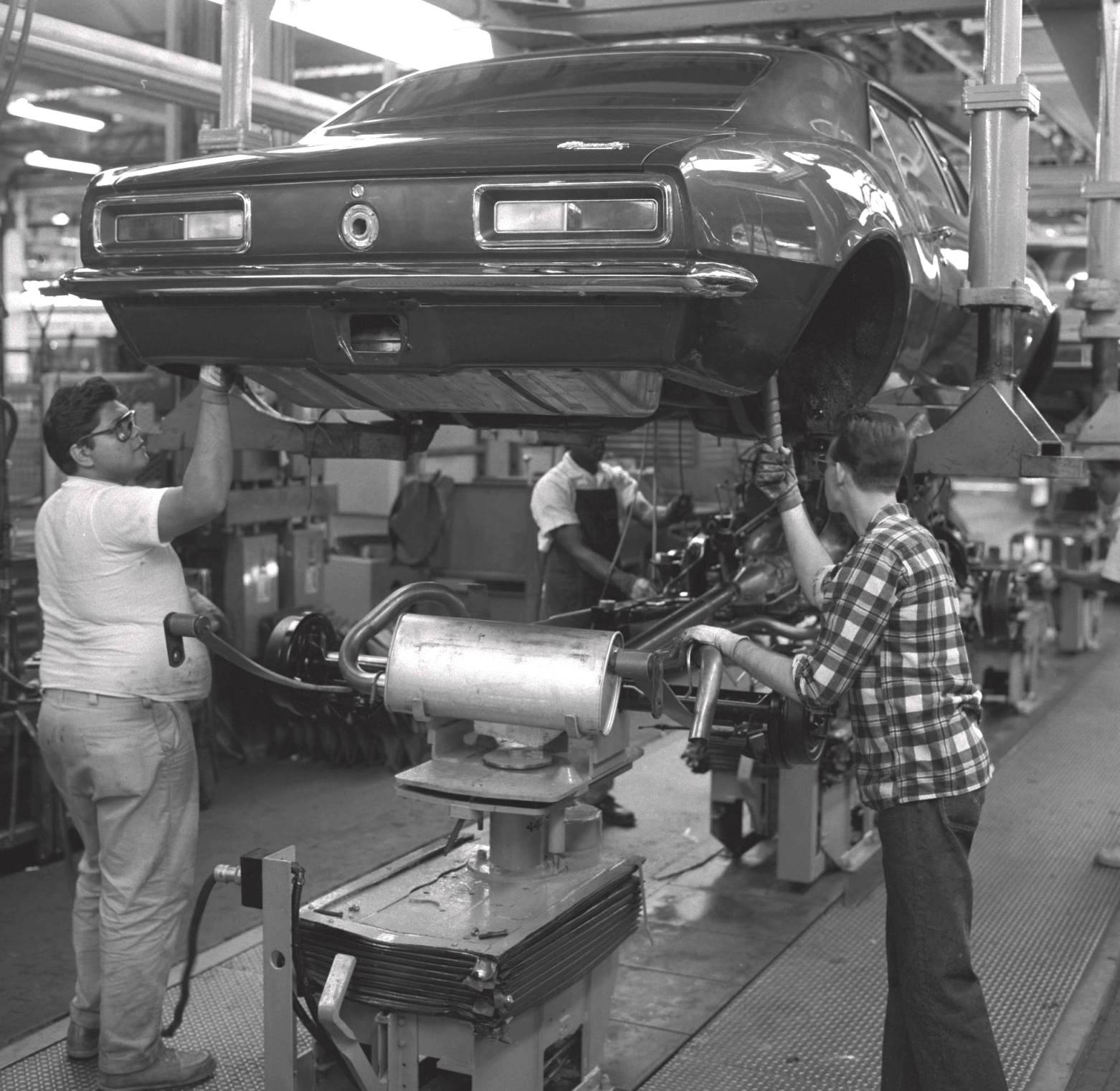
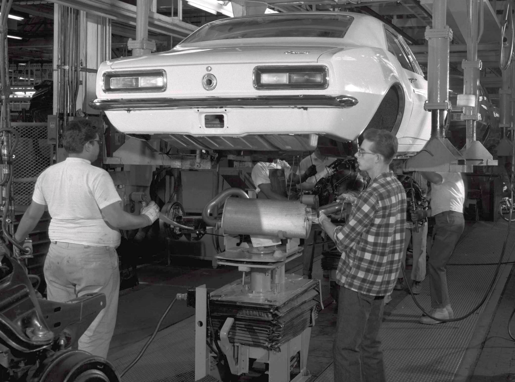
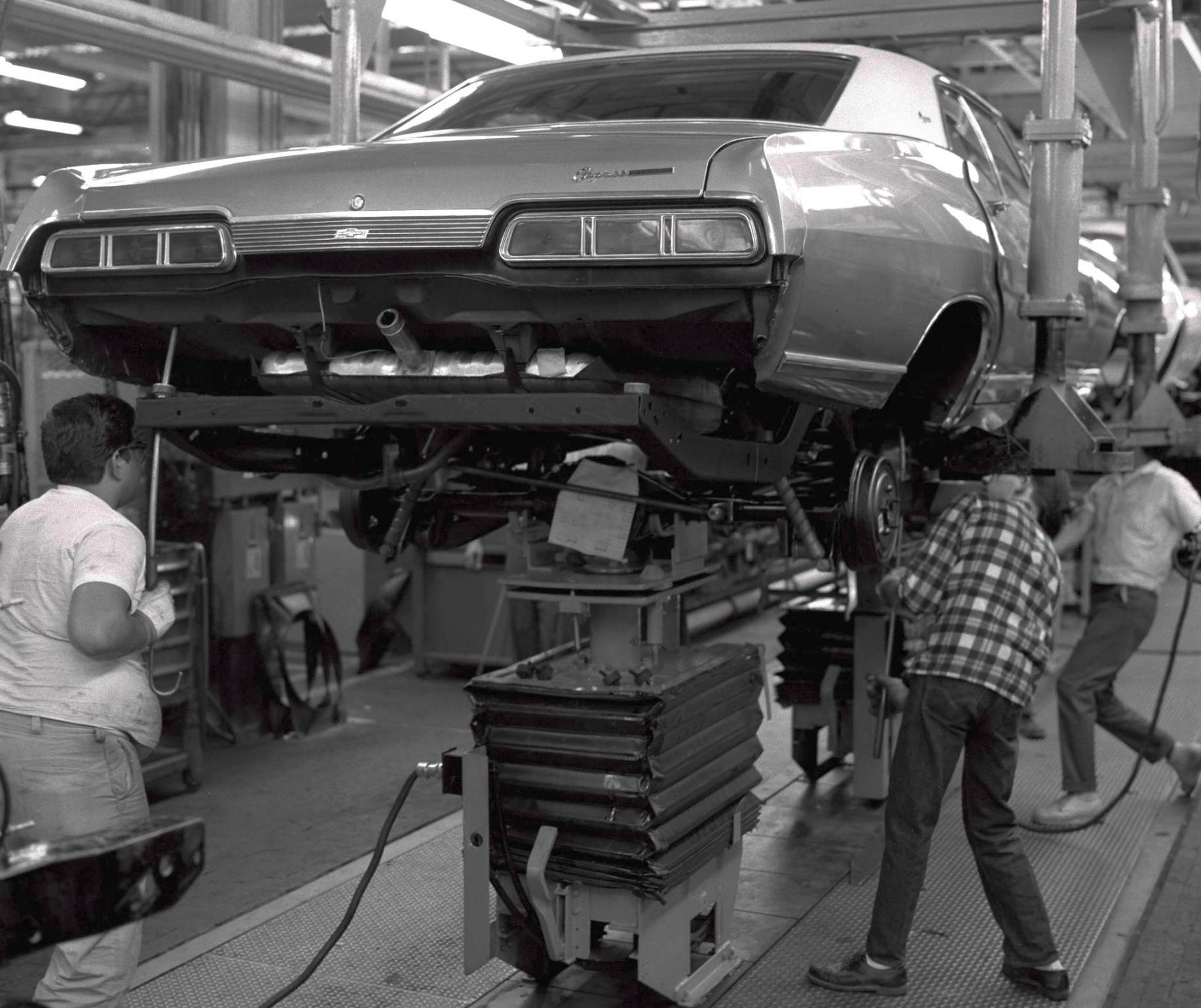
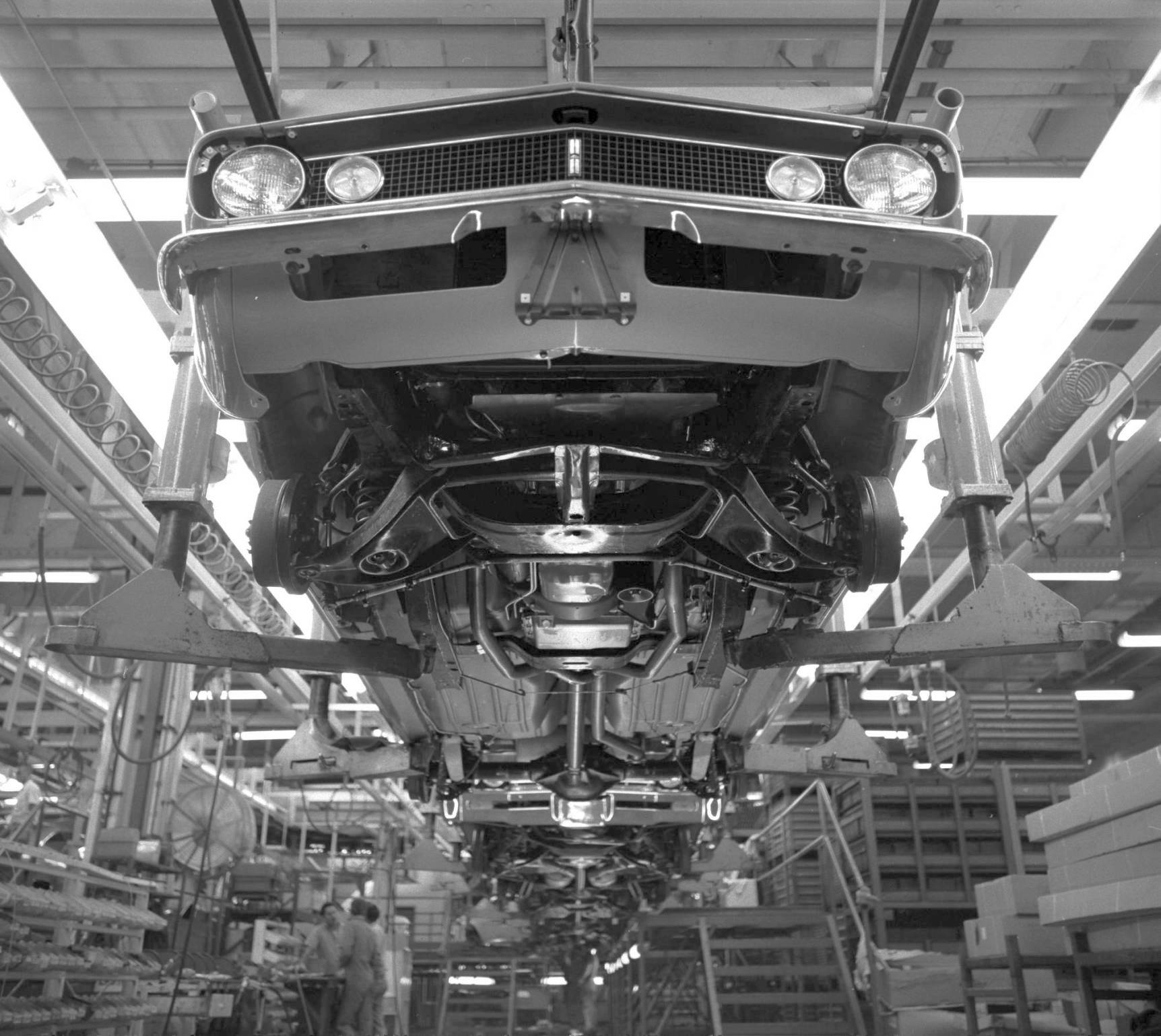
Chassis Line: Starts with the bare subframe mounted to a carrier truck, and to this is added the front suspension, steering gear and linkage (caster/camber set in a machine), rear axle and springs, fuel and brake lines, exhaust system, master cylinder (brake system bled/tested), engine/transmission, and propeller shaft. The power steering (if applicable) was then filled and the assembly sent to the Final Line on a pedestal conveyor for Body Drop at Norwood. At Van Nuys, the chassis is built-up on the Towveyor line for chassis-to-body marriage.
Paint Shop: Takes the raw front end sheet metal panels (hood, fenders, header panel, front valance, inner fenders, radiator support) from the stamping plants, welds the fender reinforcements to the fender skins, and cleans, phosphates, primes, seals, and topcoats the outer panels; cleans, phosphates and dip-primes the inner fenders and radiator support. After painting, all panels are conveyed to the Sheet Metal Line. Also has a low-temp paint system for grilles, consoles, steering columns, ashtray and glove box doors for delivery to the Trim Line, and a wheel system that primes and paints wheels and conveys them to the wheel & tire assembly area.
Sheet Metal Line: All the painted front sheet metal panels are assembled into complete front end assemblies, including fenders, header, wiring, radiators and shrouds, inner fenders, grilles, and headlights, which are conveyed to the sheet metal installation station after Body Drop at Norwood, or to the front sheet metal installation area near the end of the Trim Line at Van Nuys. Both plants installed the front end sheet metal as a pre-assembled unit (less the hood), followed by assembly of the hood.
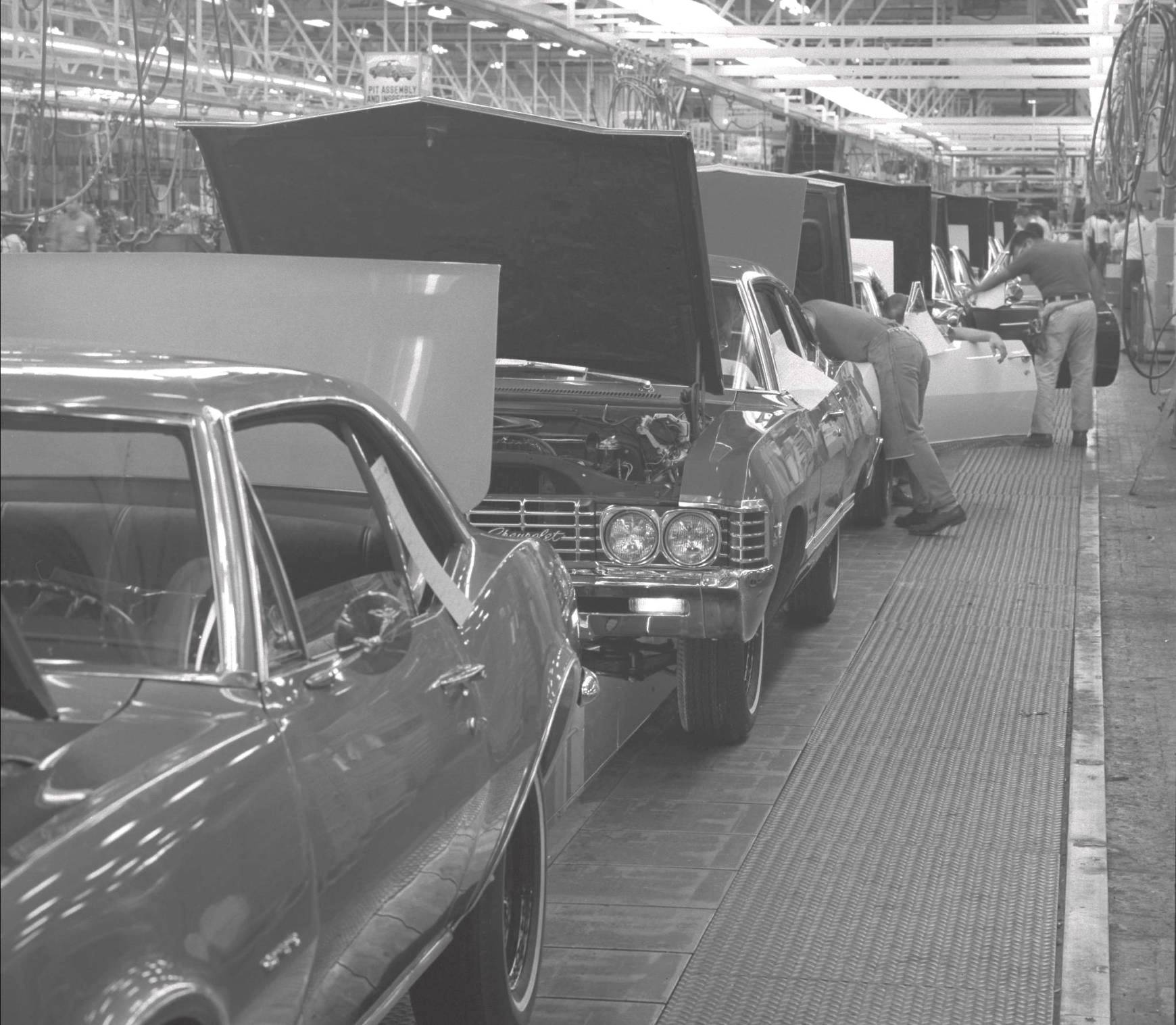
Final Line: At Norwood, the body is dropped on the pedestal conveyor-mounted-chassis, then the front sheet metal and hood are installed. At Van Nuys, the chassis is raised up to the body and secured. The rest of the Final Line process is similar at both plants - the subframe and rear springs and shocks are bolted-up, master cylinder is attached to the body or booster, mount/balance and install wheels/tires, front bumper, battery, fill cooling system, evacuate and fill A/C system, gas fill, car start, auto trans top-off, window sticker and P-O-P, drive off, toe-in set, roll-test, final inspection and repair, deliver to truck or rail shipper.
The preceding covers the basic sequence of assembly operations; now we'll cover each individual department of both Fisher Body and Chevrolet Assembly in more detail, starting again with Fisher Body, and continuing in order to completion of the car.
Subassemblies: Many major subassemblies were built up in precision off-line fixtures and conveyed to the side frame or body framing lines, including:
Underbody: The rear compartment pan, front floor pan, cowl and dash, and rear shelf panel subassemblies were welded together to form a complete underbody after being loaded to a precision steel body carrying truck on wheels with locators for each subassembly; this "build truck" carried the body all the way through the body framing line, and then returned on its continuous-loop conveyor to pick up another group of subassemblies.
Side Frame: Large assembly fixtures the length of the body were suspended vertically from a continuously-moving overhead conveyor; these were continuous-loop conveyors, one for the RH side, one for the LH side, across the aisle on both sides of the body framing line. All the body side components were loaded outside-first, in car position, and welded sequentially as the conveyor moved along, including the outer rocker, outer quarter, wheelhouse and quarter inner, front body hinge pillar, roof rails, rocker inner, and miscellaneous brackets and reinforcements depending on the body style. Separate side frame fixtures were scheduled for coupes and convertibles. At the end of the side frame line, the assembly was a one-piece body side panel, ready to be transferred into the body framing line and joined to the finished underbody assembly.
Body Framing: As the body build truck entered the framing line carrying the completed underbody, the side frame fixtures shuttled in from each side and were locked in place against locators on the build truck; two pairs of diagonal crossbars were added to tie the side frame fixtures together at the top, the upper windshield and backlite headers were loaded, and hundreds of spotwelds were made to tie the side frame assemblies to the underbody. After the headers were welded, the crossbars were removed, the cowl tag was installed, and the roof skin, tulip panel (the panel between the backlite and the deck lid opening), and rear end panel were loaded and welded. At the end of the framing line, the body was lifted and transferred to a simpler, lighter carrying truck, and the precision body build truck returned on its loop conveyor back to the underbody line.
|
|
Body-In-White Final Operations: The side shroud ("saddlebag") outer panels and the doors and deck lid were installed and fitted, followed by soldering and metal-finishing the roof-to-quarter joint, metal-finishing exposed spotweld flash, stud-welding for windshield and backlite and vinyl top molding retainers, option and spoiler drilling, mig-welding the dual exhaust hanger (for 1969's, if applicable), final metal-finish, body cleanup, and inspection. Once complete, the body and loose cowl vent panel were shipped upstairs to the Paint Shop.
Most Body Shop repairs were handled on-line (dings, dents, metal-finish, solder repairs, missing weld studs, missing welds, etc.), but there were off-line stalls for major metal repairs, panel replacement, and similar issues that required the body to be stationary for an extended period.
Phosphate System: The raw body shell passed through a seven-stage phosphate system, where it went through a series of enclosed high-pressure hot spray stages where it was washed to remove all the oils and debris from stamping, welding, brazing, soldering, and grinding operations, then the body was coated with a hot iron phosphate solution which "etched" the metal and provided "teeth" for paint adhesion. The final stage was a de-ionized hot water rinse and blow-off, followed by a drying oven on the way to the prime booth.
Prime System: In the first prime booth, the entire body, inside and out, was manually sprayed with primer, and confined areas subject to corrosion were given a second coat of heavier primer material; this prime coat was then baked at 390F for 30 minutes. In the second prime booth, the instrument panel and rear of the shelf area (and the upper door and quarter areas of 1967-68 models) were painted interior color, and another coat of air-dry flash primer was sprayed from the belt line down. The interior color areas were masked, and the entire outer body was sprayed with gray primer-surfacer and the body was baked again at 285F for 45 minutes. The cowl vent panel was hung in the side window opening on wire hooks all the way through the paint process.
After baking, the entire outer surface was wet-sanded, wiped down, and the body went through a short infra-red dry-off oven on its way to the sealer deck.

|
Sealing: The primed and baked body passed through a long series of platforms where vinyl plastisol sealer was applied to all joints; floor pan drain hole plugs were installed and sealed, and the sealers were manually dressed in exposed areas. Floor pan deadener pads were then installed, which "melted" into place later in the color reflow oven. The body then went through a sealer oven to "set" the sealers on its way to the color booth.
Color System: The bodies were sequenced to "batch-paint" by color as much as the build schedule allowed, to minimize the waste of thinner required to clear paint guns between colors. The interior was masked off, the body exterior was tacked-off, and it then entered the main color booth, where it got three coats of acrylic lacquer, sprayed automatically with vertical and horizontal reciprocating spray guns, with a 3-minute "flash" between coats, followed by a 10-minute bake at 200F to "skin" the surface prior to sanding. In the next stage, any surface defects were power- and hand-wet-sanded with mineral spirits, then wiped off prior to entering the final "reflow" oven. This bake lasted 30 minutes at 275F, where the lacquer surface softened and "re-flowed" to a uniform gloss.
The last process for a non-stripe car was the blackout booth, where the firewall was blacked-out, the trunk was sprayed with spatter paint, and sound-deadening undercoat material was sprayed in the rear wheelhouses. The rear "cocktail shakers" on convertibles were suspended in the trunk for spatter painting, but weren't bolted in place until later in the Trim Shop, after the taillights and marker lights were installed.
If the car required Z28, Z10, or Z11 stripes or a black rear end panel or rockers, they were masked and manually sprayed in the in-line repair booth/oven system after the reflow oven, including the cowl vent panel; spoilers were painted body color separate from the body, and were final-installed to the deck lid just prior to the repair booth. The rear window filler panel, deck lid and spoiler were masked and sprayed stripe color in the repair booth, and baked in the repair oven before the body went back downstairs to the Trim Shop. The paint guns in the repair booth were fed from manifolds that were part of the main color circulating system so that the repair booth used exactly the same paint the main color booths were using.
If a unit required a major paint repair that couldn't be accommodated in the normal in-line cycle time, it could be diverted off the main line at the end of the repair booth into a parallel loop that ran in the opposite direction and fed the unit back into the main line ahead of the main repair booth; the re-run loop could accommodate about 20 units.
Paint came from DuPont in 500-gallon tote tanks, with paint mixed from the same lot distributed to both the Fisher and Chevrolet paint shops to minimize color match and gloss issues between the body and the front sheet metal.
Special order paint colors were done by dragging 5-gallon pressurized paint pots through the booths and manually spraying everything; if there was a fleet or special order large enough, they charged one of the spare circulating systems, but that didn't happen very often - it didn't pay to charge a spare system for less than 100 cars.
Wiring and the roof insulator went in first, followed by the headliner and sail panel and shelf trim and garnish moldings (and rear speakers or defroster if ordered), and the windshield and backlite opening flanges had the molding clips installed and were primed for later glass installation (vinyl tops went on ahead of this so the rear edge could be trimmed in the backlite opening before glass priming). Convertible windshield frame trim moldings and latch hardware were installed, along with the power top mechanism, plumbing, and wiring.
Convertible tops were built up on an off-line merry-go-round fixture, then carried to the line where the installation was completed; a protective shipping cover was installed over the top skin after final inspection before the body was shipped to Chevrolet.
Door and deck lid locks were installed. The lock/key package was a Fisher Body item picked at random out of a bin - it came in a 2-part bag; Fisher tore open the half with the door and deck lid cylinders and installed them, and taped the other half of the bag to the instrument panel; the Chevrolet Body Bank entry clerk tore the label off the bag (which had the key numbers on it) and input those numbers (along with the body number that associated the body to the ident number and dealer order) to the program that generated the Broadcast Copy, which had the key numbers on it when it was printed. When the body got to the Chevrolet Trim Line, the glove box cylinder was installed with the (Chevrolet-painted and assembled) glove box door, and the ignition cylinder was inserted when the steering column was installed. The second set of keys was placed in the ash tray.
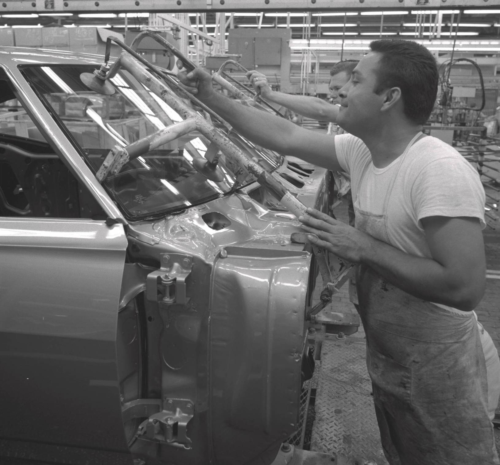
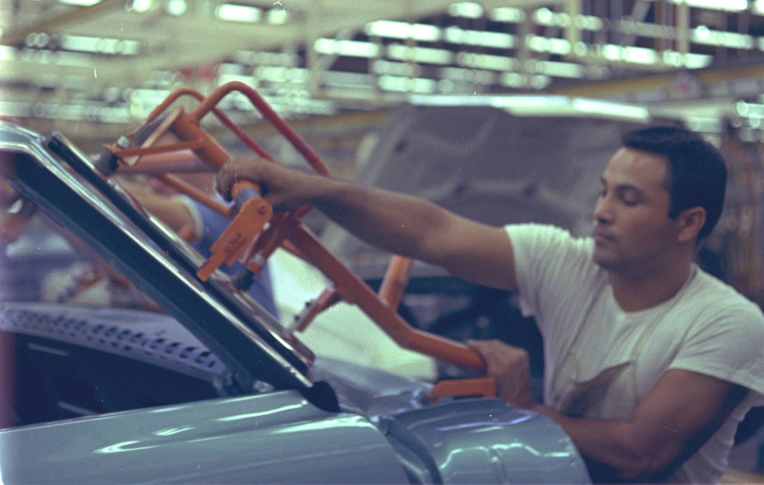
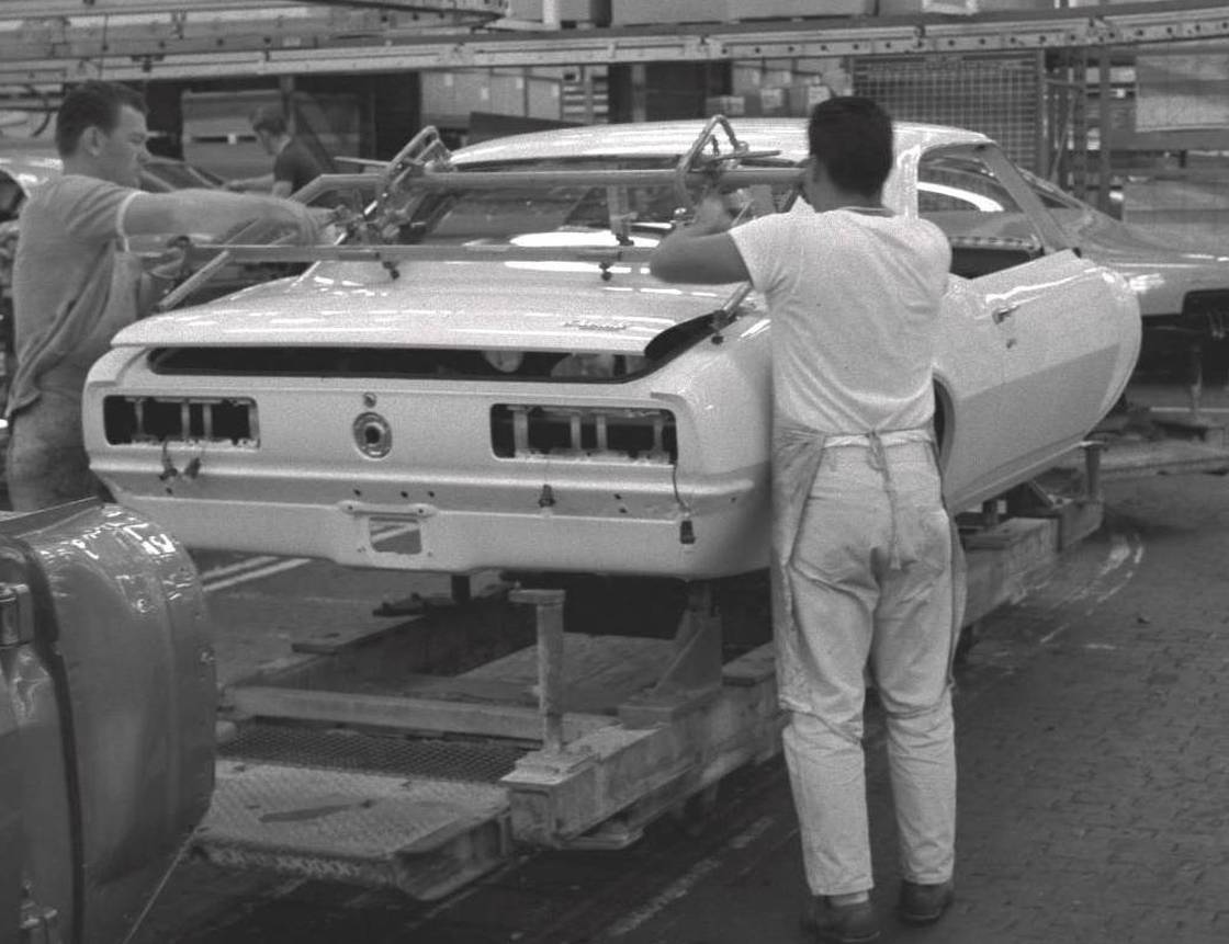
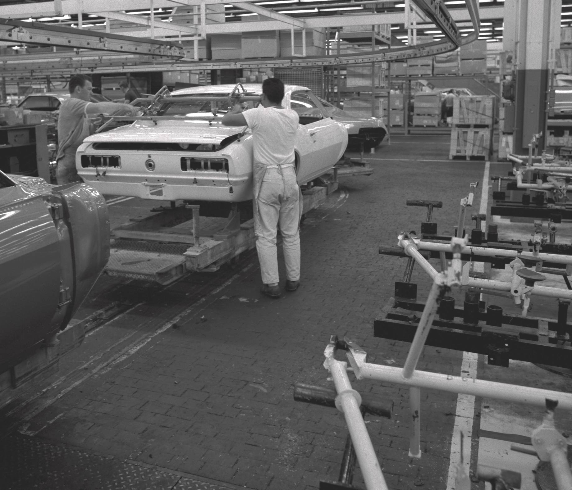
Door and quarter panel interior hardware and side glass went in and glass was set to gage blocks on the windshield pillar and roof rail, and roof rail and door opening weatherstrips and drip moldings went in next. After verifying side glass fit, door and quarter trim panels and kickpads were installed. The windshield and backlite glass was cleaned, primed, and had the dam and Thiokol adhesive bead applied, and were installed in the openings, followed by "bear grease" sealer between the bottom edge of the glass and the edge of the opening, and the reveal moldings were installed; the gage-located cowl vent panel was used to locate the ends of the lower windshield reveal moldings, and was left secured by one screw. Taillights, marker lights and emblems were installed (followed by the rear "cocktail shakers" on convertibles), sealing fixtures were clamped over the firewall holes, and the body went through a 3-minute water test booth and inspection area. The seats for that car were delivered from the "Cushion Room" where they were built, and the rear carpet and seats were installed last, followed by a final inspection (at Norwood, but not Van Nuys, "P", "T", and "B" ink stamps were applied to the body for Paint, Trim, and Body inspection OK), and the body was shipped up the ramp to Chevrolet.
Order reference: When the body entered the area, the clerk entered the body number from the cowl tag and the newly assigned VIN into the computer, which cross-referenced back to the "ident number" and dealer order number. This data resulted in generation of the precise specifications and all the Chevrolet parts required for that particular car and prepared the file that would generate the "Broadcast Copy" when the car was released.
Scheduling: There were usually six lines in the schedule bank - one for RS, one for A/C, one for SS and Z/28, and three for high-volume standard cars, so cars could be scheduled without having situations like three A/C's in a row, three consoles in a row, three RS's in a row, etc., as these had higher work content vs. the standard cars and scheduling two or three of them in a row would over-cycle certain line operations.
Releasing: When the clerk at the end of the body bank selected the next body based on the scheduling "rules" and released it from its line into the main conveyor to the Trim Line, the computer released the "Broadcast" file with the next sequence number, and it was sent to many teletype printers throughout the plant where subassemblies were built and sequenced for delivery to the Main Line to meet up with that particular car. The same computer program also generated the end-of-line paperwork for that car - the price sticker, car shipper, and other internal documents. Note that as the bodies were released from the six lines in the body bank, the bodies were not in VIN order.
The "Broadcast Copy" (often called the "build sheet" today) included the sequence number, VIN, identification number, dealer code, order number, and selection codes for virtually every part that went on that car. There were two types of Broadcast Copies: the Body Broadcast Copy (BBC) was used on the Trim Line and Final Line, and the Chassis Broadcast Copy (CBC) was used on the Engine Dress, Chassis, and post-marriage overhead Chassis Line. There was some level of duplication on both Broadcast Copies, which were standard Chevrolet forms used in most Chevrolet plants. (Vega assembly at Lordstown was a notable exception - the teletype printers couldn't print a full sheet at 103 per hour, so the Vega Broadcast (designed by yours truly) was only a half-sheet, 8-1/2 by 5-1/2 inches, so the printers could stay ahead of the line.) By the time the car got to the Final Line there were Broadcast Copies all over it, under it, and inside it, as all the various feeder lines used them too. Each installation point for conveyor-delivered components had a trash barrel to pitch the copy that came taped to the subassembly, and there were several at the end of the Final Line.
The car was now officially released for production, and was locked permanently in sequence as it headed for the Trim Line. At Norwood, the body was on a Trim Truck, and at Van Nuys it was in an overhead conveyor clamshell carrier (the low ceilings in the old Norwood Trim Shop building weren't high enough to accommodate overhead conveyors).

|
Next came the Z87 wood-grain trim plate and assist handle, parking brake bracket, dimmer switch, speedo cable and grommet, accelerator pedal and lever, and the pedal support assembly (and booster with power brakes), plus the clutch pushrod and pushrod seal on manuals, followed by the A/C air distribution and outlet ductwork and the upper instrument panel pad. The instrument cluster was subassembled in an off-line conveyor system, including the instrument panel wiring harness and fuse block, and was installed next, followed by routing the wires, securing the fuse block to the dash panel, and attaching the heater or A/C control head to the cluster. Subsequent operations included the radio, ash tray assembly, and glove box and door, followed by the steering column with the wheel already subassembled to it, then the front carpet and sill plates. Holes were drilled for the console, automatic floor shifter and cable, the riv-nuts were set, and the shifter was installed. The floor console went in next, less the upper trim plate, shift boot, and retainer for manuals, which were installed on the Final Line after Body Drop. The cowl vent panel was retrieved from the back seat, its front seal was added, and it was final-installed on the cowl, followed by the wiper arms and blades.
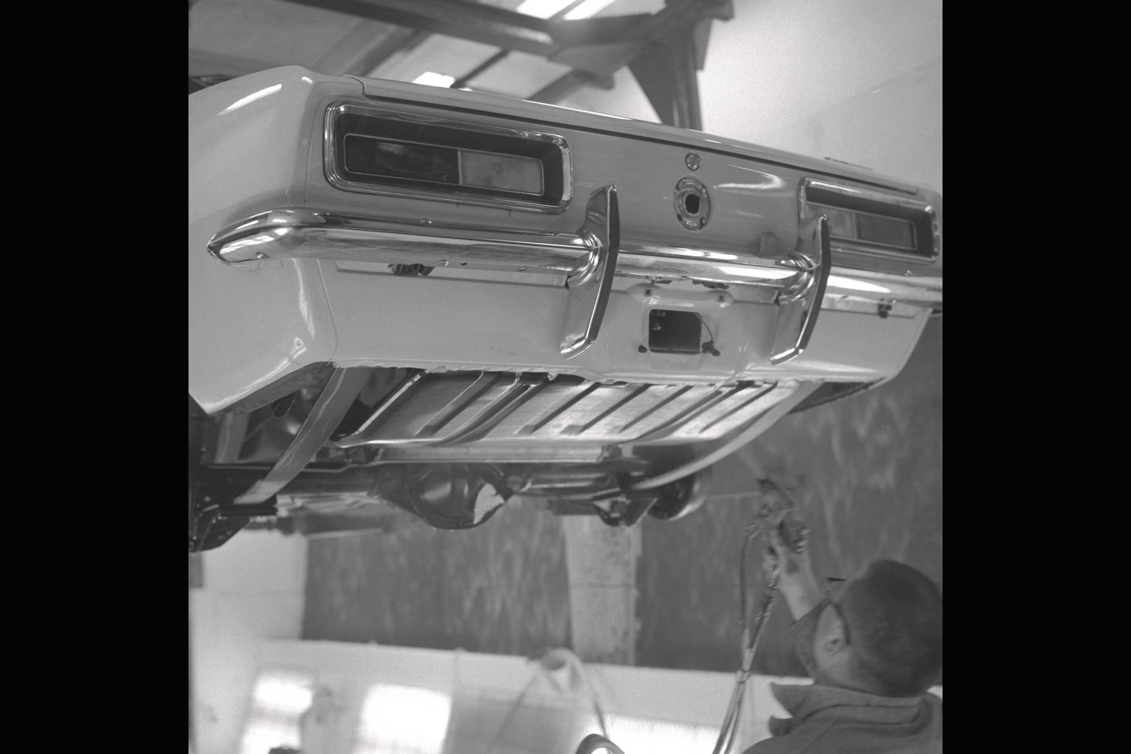
The rear bumper and guards, RS backup lights, license door and license light were installed, followed by the heater hoses, fuel tank, rear shocks, pinion bumper, and rear spring front U-nuts and rear shackles and upper shackle bushings, and the trim operations were complete.
FRONT SHEET METAL PROCESSES IN GM PLANTS
In GM assembly plants in the 60s and 70s, there were three different processes for installing the front sheet metal to the body. This depended on the plant's history and the type of vehicles it produced.
Most plants (including Norwood) installed the front sheet metal on the Final Line after body drop, although two different methods were employed. Some plants (including Norwood) installed the front sheet metal as a complete one-piece "buck-built" assembly after body drop, then installed the hood last. Other plants installed the front sheet metal "piecemeal" after body drop - radiator support and header/grill first, then the fenders, then the hood. Lordstown used this "piecemeal" process for their combined Impala/Caprice/Firebird build.
The Van Nuys partial-frame "F" body and full-frame "B" body front sheet metal installation was laid out following their pattern of previously building fully-unitized bodies. They also buck-built the front sheet metal assembly as a single unit, but installed it to the body on the Trim Line, with the body supported in an overhead carrier. The hood was fitted last, prior to their Towveyor chassis-to-body marriage operation.
As passenger car frames disappeared and fully unitized body construction became the norm in the 80s, 90s and beyond, all of the front sheet metal was installed in the Body Shop.
|
|
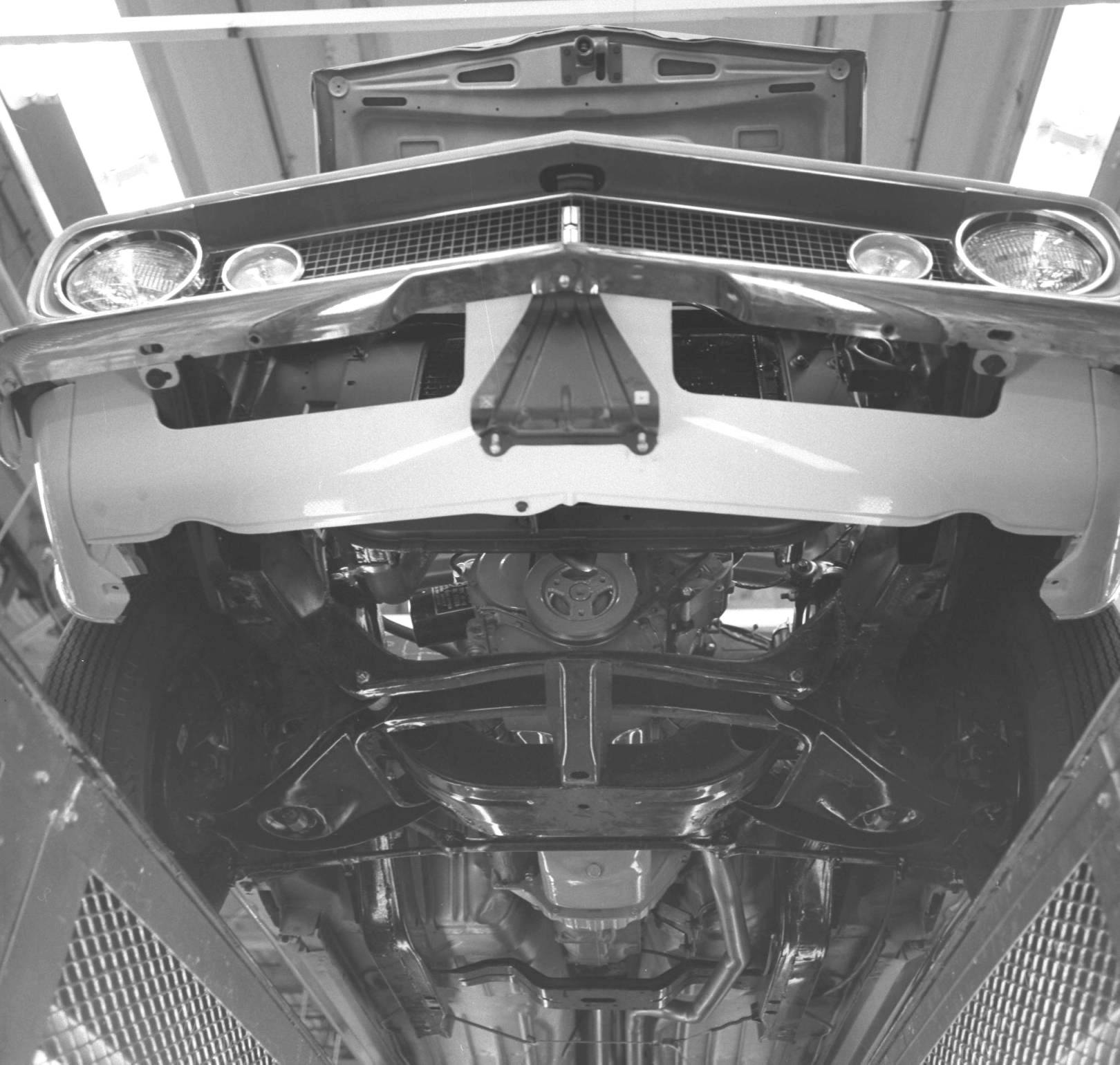
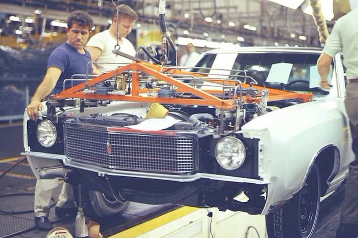
The "buck-built" front clip was lowered into place with an overhead hoist; two operators guided it into position, pulling the rear of the fenders outboard to clear the side shroud "saddlebags" on the body as the assembly moved rearward. The hook was then released and the hoist went back upstairs to pick up the next assembly. At this point, operator skill became critical as the shim packs were made up and stuffed in place for the top, front, side, and bottom fender-to-body attachments to achieve the correct gap and flush fits between the fenders and the body.
Establishing a perfectly square hood opening was critical, as the hood was "trapped" on all four sides by the header, fenders, and cowl vent grille; a special "hood squaring fixture" (similar to this fixture on a Monte Carlo) was dropped in place. It had two pins at the rear that went into the two holes in the cowl just inboard of the fenders (the ones with the little black plastic plugs in them), two pins at the front that engaged the two holes in the top of the radiator support just inboard of the diagonal brace attachments, and locator blocks on the sides for the fenders. Once the fender fit points at the rear were properly shimmed and secured, the squaring fixture was removed, and the front end was ready for the hood.
The last step prior to hood installation was to retrieve the antenna body from the R.H. hinge pillar and install it to the fender.
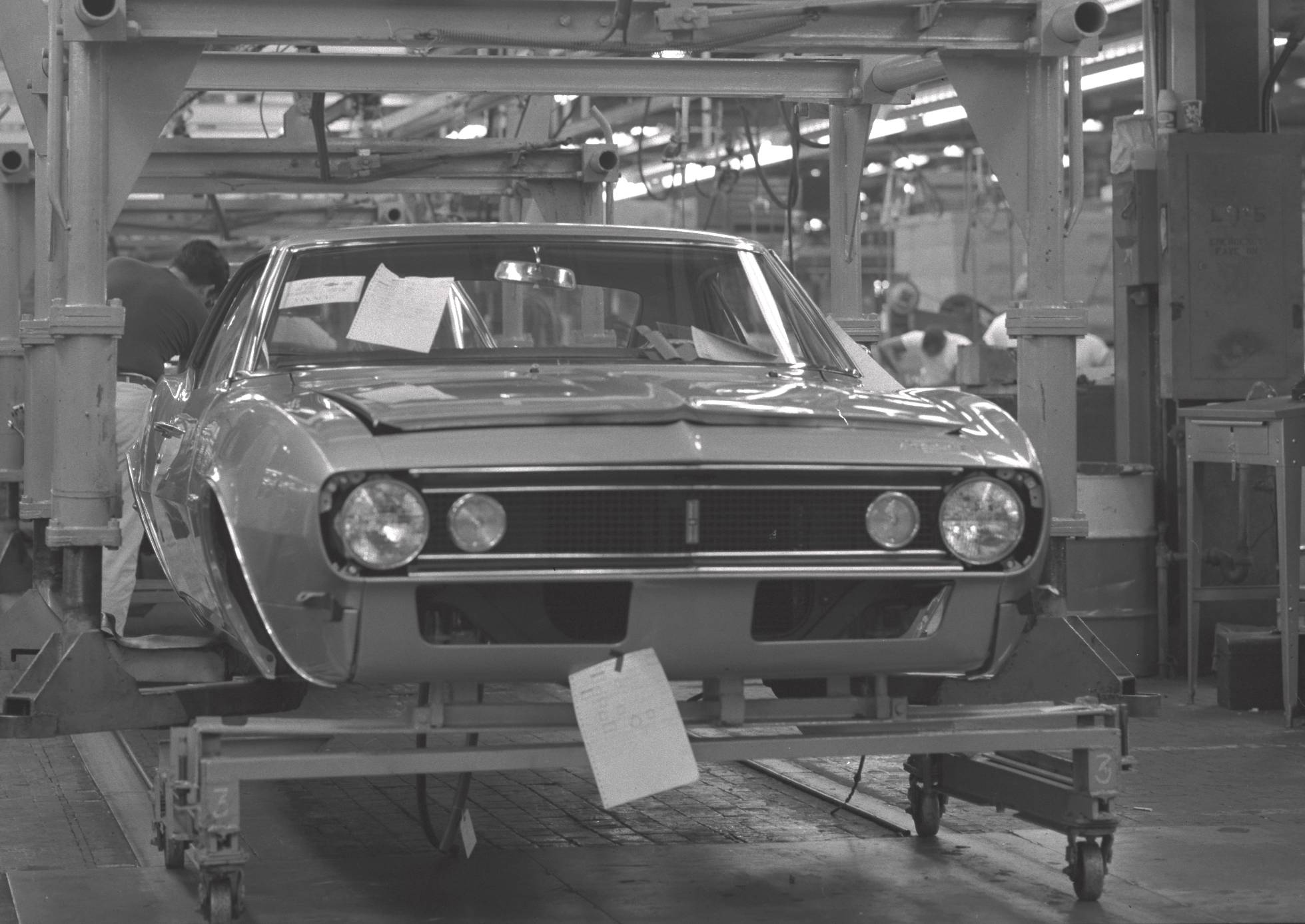
From this point, the body was conveyed to the Final Line, where it would meet the chassis.
|
|
|
|
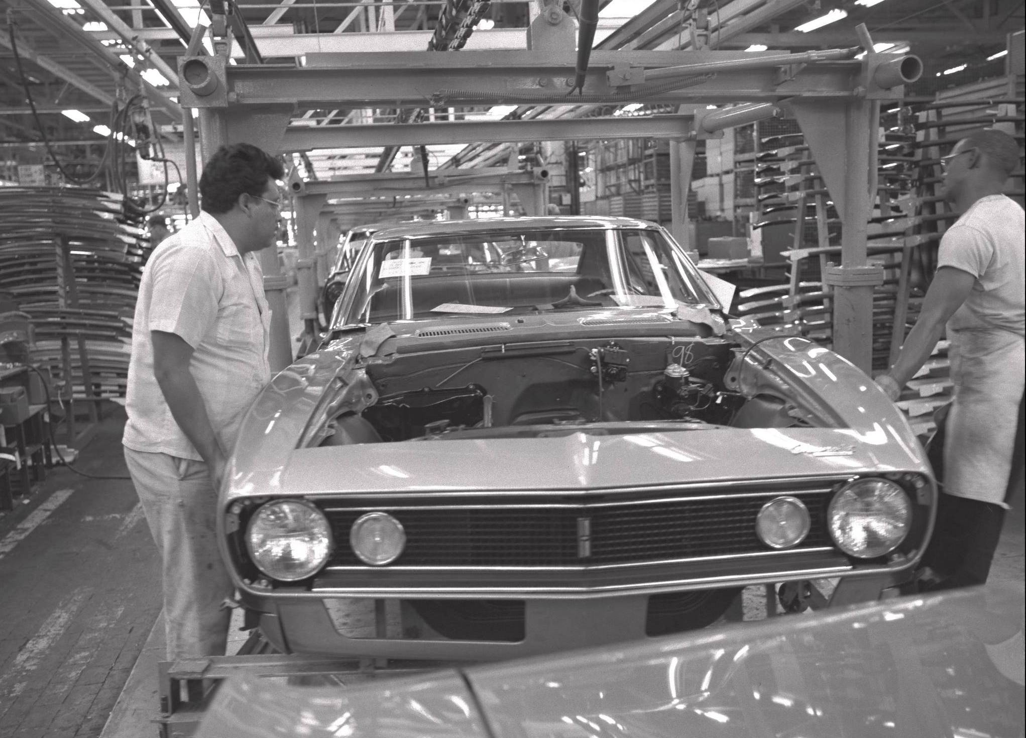
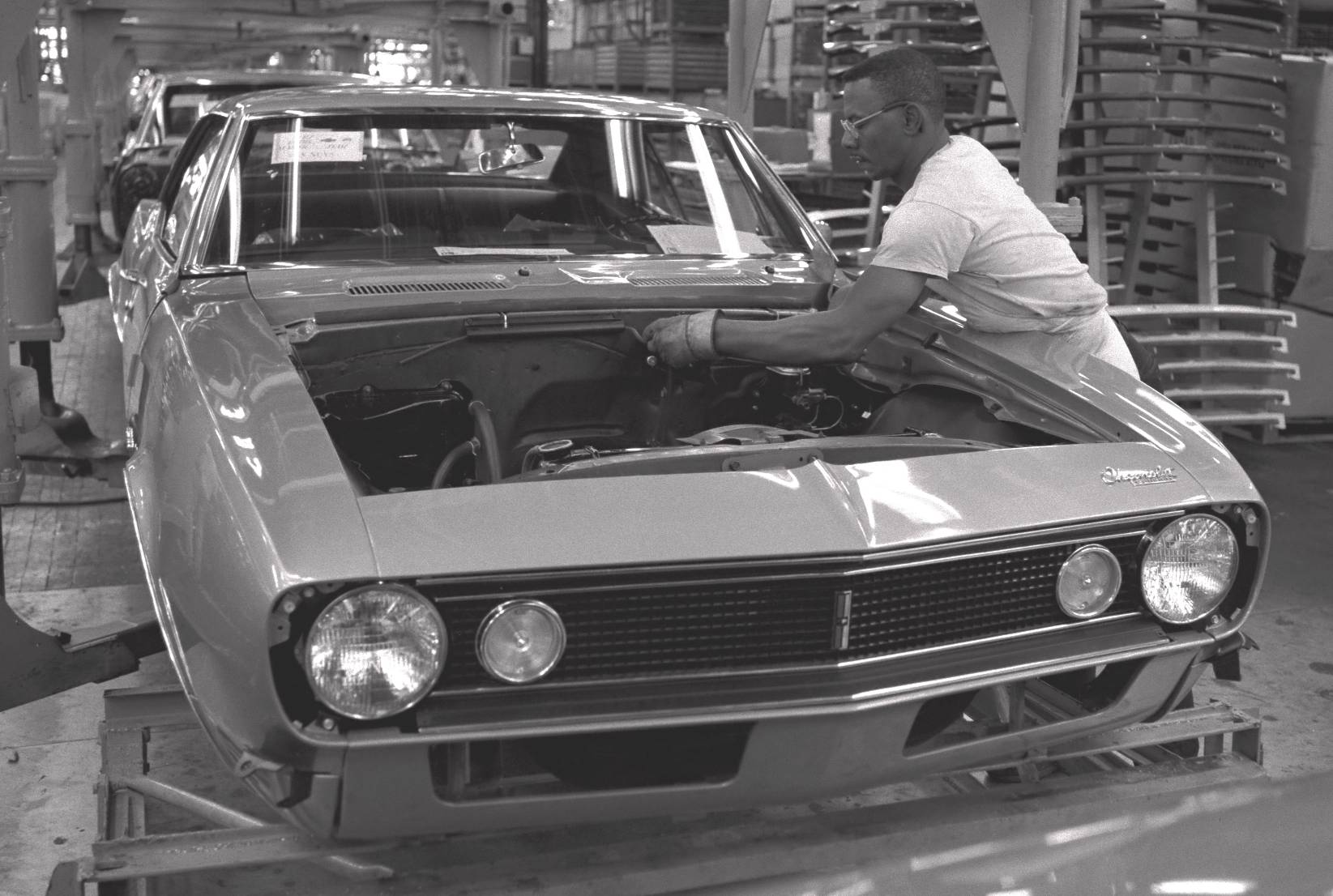
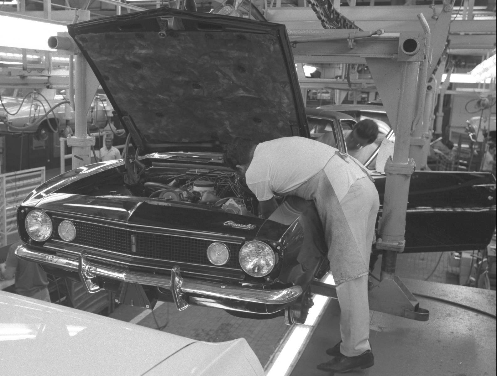
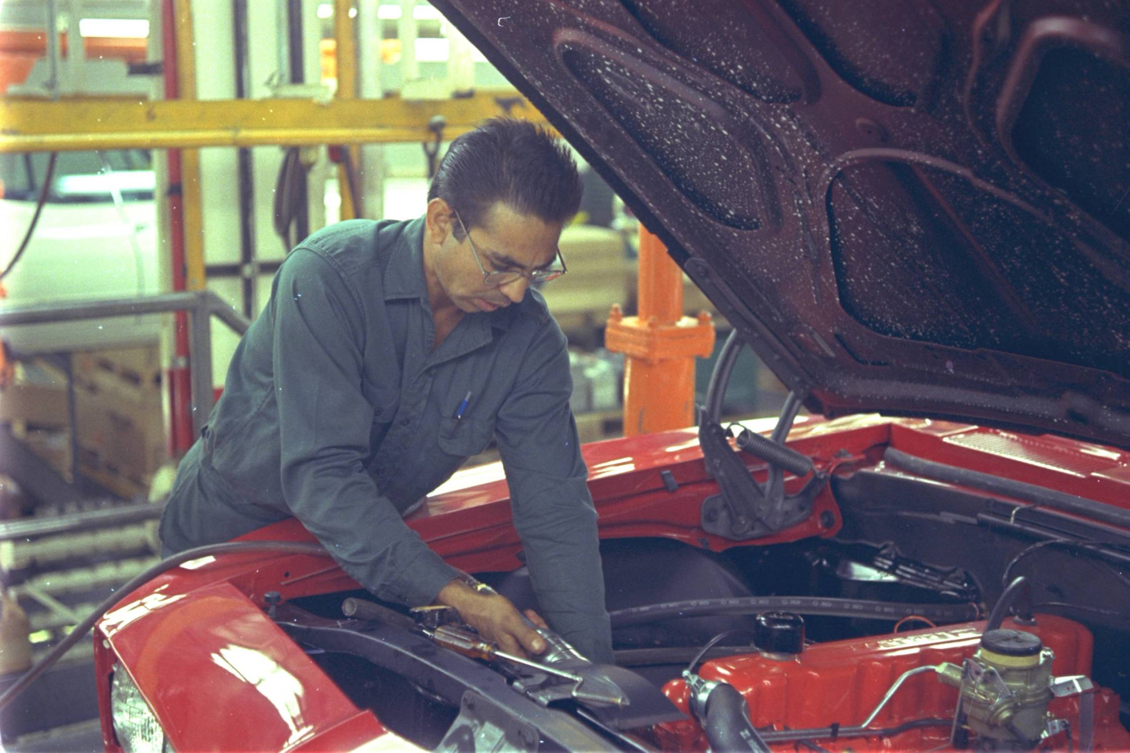
In the engine schedule area, the operator grabbed the next Broadcast Copy from the printer, verified the sequence number, noted the engine code required for that car, and moved an air-powered overhead hoist on traveling bridge rails over the correct engine rack. The specified engine was hoisted out of the rack and transferred to the next hook on the overhead engine dress line conveyor, where the throwout bearing (on manuals) was greased and installed, along with the clutch fork boot. Another operator on the other side of the line repeated the process with the specified transmission, which was then installed and bolted to the engine; on automatics, an air tool was used to rotate the flexplate, and the converter bolts were driven, followed by the lower cover.
The VIN derivative numbers were stamped in the next operation on both the engine pad and the transmission, using a gang-stamp holder and a hammer. From here on, all the detail dress items were added (plug wires, coil, engine harness, battery cables, carburetor, pulleys, alternator, starter, fan and clutch, A/C compressor, power steering pump, transmission cooler lines and fill tube, A.I.R. pump, diverter valve and air manifolds, drive belts, dipstick and tube, oil filter, engine and transmission mounts, PCV plumbing, vacuum fittings, fuel pump and fuel line, radiator hoses, and (if applicable) the transmission-mounted 4-speed manual shifter and linkage was installed and adjusted (3-speed manual floor shifters were mounted on the cross-member and adjusted later on the Chassis line). Engine oil and transmission lube were added, and the completed engine/transmission assembly was conveyed to the Chassis Line for installation in the subframe. The engine line inspector wrote the engine, transmission, and carburetor codes on the Broadcast Copy and put the sheet in a box for pickup by a Scheduling clerk (needed to create the P-O-P at the end of the Final Line).

|
The subframe was built up separately on a feeder line; the bare subframe was loaded on a conveyor, where the frame-side engine mount brackets were installed. Next, the upper and lower control arms and stabilizer bar were loose-installed, followed by the front springs and hub/spindle/brake caliper assemblies. It was then loaded into the "Geo-Machine", which set caster and camber. The machine clamped the subframe down solid against locators, and a swiveling head on each side was bolted to the front hub lug studs; when the machine was cycled, the machine heads compressed the hubs to design suspension height and positioned the wheel mounting face of the hubs to the correct caster and camber angles, which created gaps between the upper control arm shafts and the bracket on the subframe. The operators stuffed both gaps on each side with shims positioned over the studs, and torqued the nuts on both sides and the bushing bolts through the lower control arm bushings, plus the stabilizer bar bushing and end link bolts; the machine then lowered the suspension to full rebound against the upper control arm bumper, the nuts were removed holding the machine heads to the hub faces, and the subframe was transferred out of the machine, flipped upside-down, and the steering gear, pitman arm, idler arm, and steering linkage were installed. The subframe was then flipped right-side-up and loaded on the chassis carrier truck.
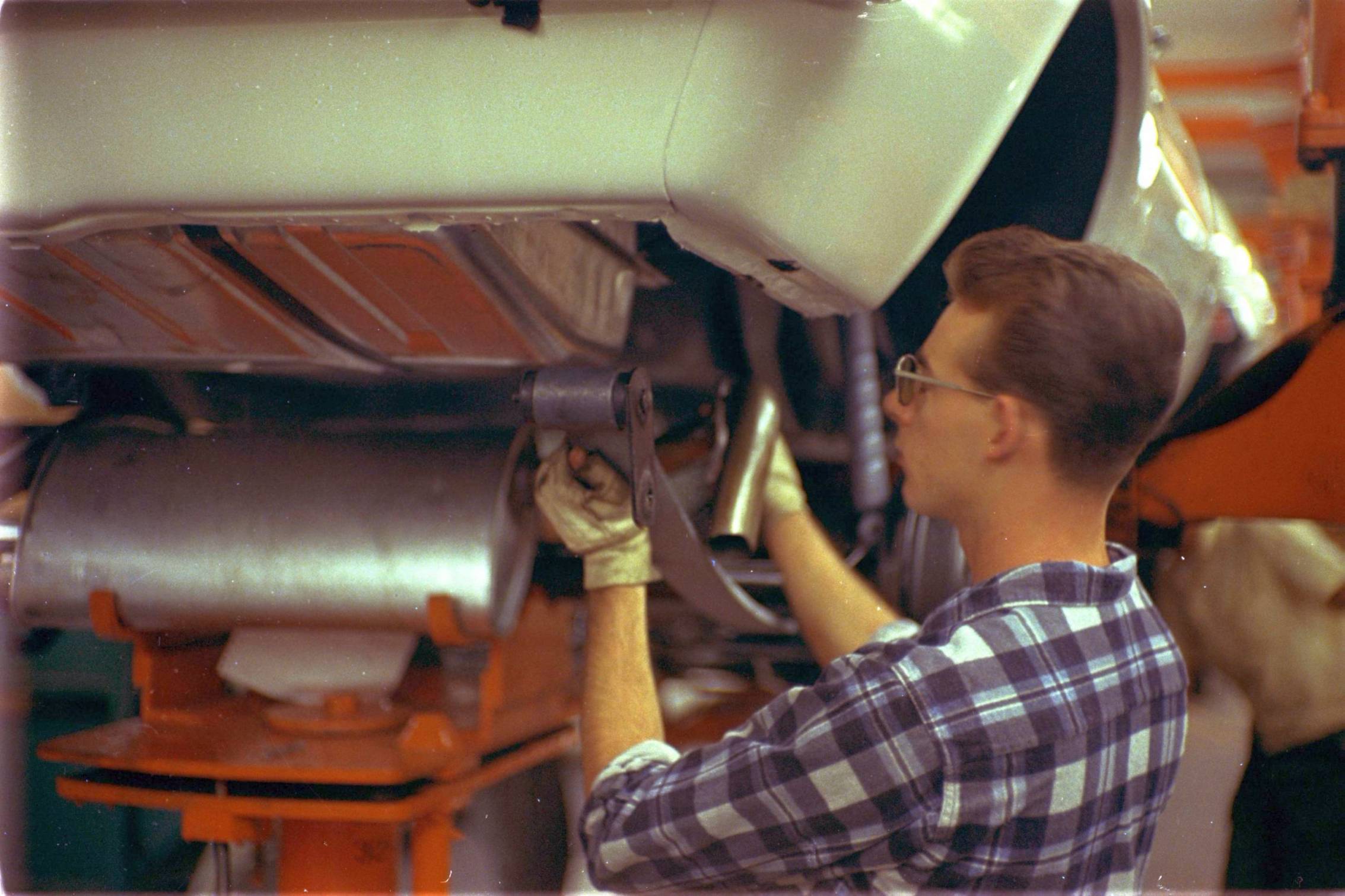
The rear axle, rear brake pipes, and rear springs (including the front mounting bracket, bushings, and fully-torqued through-bolt) were subassembled (and the diff lube was added) on another feeder line, and that unit was then loaded on the chassis truck, followed by the front shocks, prop shaft, brake pipes, valves, hoses, and master cylinder, transmission control and backdrive linkage, fuel and vapor lines, and the engine/transmission assembly was installed and all mounts were torqued. The power steering hoses and fuel/vapor lines were connected, the clutch cross shaft was added, manual floor shift linkage was installed and adjusted, and the heat riser valve and complete exhaust system was installed.
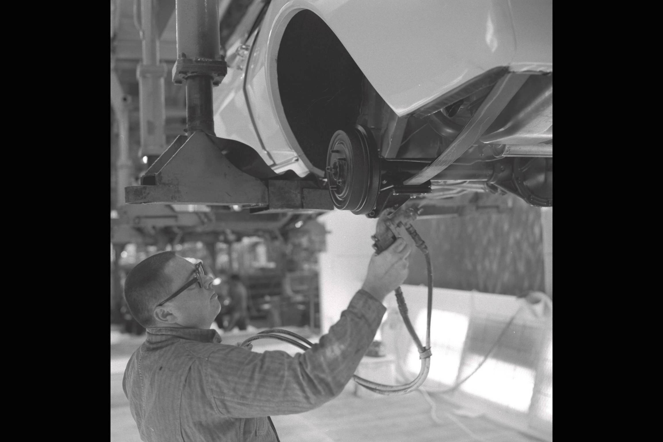
The chassis then passed into the fluids area, where the power steering system was evacuated and filled automatically, and the brake system was evacuated-and-filled automatically through the master cylinder - the bleeders on the master cylinder and at each wheel were never touched. Another machine head was then clamped to the back of the master cylinder which pushed on the rear piston to bring the brake system to 1200 psi and held it there for 20 seconds; any pressure decay or movement of the piston indicated a leak. When the leak test was complete, the machine automatically topped-off the fluid level, the test head was removed, and the master cylinder cap was installed. The inspector then wrote the axle number on the Broadcast Copy and set it aside for later pickup by Scheduling, and the complete chassis moved on to the Final Line Body Drop station at Norwood or to the Towveyor lift station at Van Nuys.
Raw Metal: The front fender outer skin and the long inner fender reinforcement were received separately from the stamping plant in order to get more pieces in a standard rack; these two parts were spot-welded together in special fixtures which established the "crown" of the fender so it matched the contour of the hood, and the raw welded assembly was then sent to the primer "Flow-Coat" line.
Sheet Metal Painting: All raw parts (wheels, brackets, etc.) and the front end sheet metal (hoods, fenders, lower fender extensions, header panels, front valances, radiator supports, inner fenders, etc.) went through a cleaning, degreasing, and hot phosphate system, then through a flow-coat booth where it was deluged with black primer from all directions and then baked. The sheet metal parts that got exterior color were pulled off the prime conveyor and loaded on another conveyor buck, in car position, for finish painting; it got a coat of primer-surfacer that was baked and lightly wet-sanded, then got three coats of lacquer, a short bake to "skin" it over, a light wet-sanding and wipe-down, then it went through the final re-flow oven at 275F for 30 minutes. Next was an in-line repair booth where Z-10/Z-11/Z-28 and D-90/DX1 stripe masking, spraying, and de-masking was done (including lower fender blackout when required), followed by another oven. After cooling, the conveyor delivered the buck carrying the color-coated parts, in the same sequence as the cars on the main assembly line, to the sheet metal subassembly area. Exterior color lacquer was supplied by DuPont, and both Fisher Body and Chevrolet Paint Shops at the same assembly location were supplied from the same DuPont-mixed lot in order to minimize any color-match problems. This wasn't an issue at Van Nuys, as their recently-consolidated Paint Shop had each car's front sheet metal on a buck just ahead of the body shell so the entire exterior of the car was painted at the same time with the same paint; that set of sheet metal eventually met up with that same body again after Body Drop on the Final Line.
Wheel Painting: The wheels were removed from the prime conveyor and placed in another conveyor system that took them through a booth where their faces were sprayed with color wheel enamel, then through an oven, and the conveyor continued to the wheel & tire assembly area where the wheels were picked off.
Small Parts Paint: All the miscellaneous brackets and small parts that only got black primer were picked off the prime line after cooling and were placed in individual containers by part number for delivery to the engine, chassis, and final line areas where they were installed.
Low-Bake Paint: Small plastic and metal parts that required color (grilles, consoles, steering columns and covers, N34 steering wheel hubs, ashtray and glove box doors, stereo speaker grilles, etc.) were received in prime from the suppliers and were painted in yet another paint system, in build sequence, baked at 150F in a short infra-red oven, and conveyed to their point of use on the Trim Line and the sheet metal subassembly area.
VE3 Front Bumpers: These optional front bumpers were received already painted from the supplier, as they required a special flexible paint and a unique process not available in the assembly plants.
Final Paint Repair: There were no paint operations of any kind after the finished car came off the Final Line, unless it needed a repair that couldn't be finished in the Paint Shop or if it got scratched during the assembly process after paint. If a spot color repair was required, it was done in an off-line prep area and spray booth with an infra-red oven which only heated the repaired surface to about 150F ("low-bake"), and final gloss of the repaired area was achieved by compounding and polishing.
The radiator support was built up first and placed on the conveyor fixture, including the radiator, A/C seals, baffles, condenser and plumbing, center grille support, hood latch assembly, horns, header panel, voltage regulator, horn relay, headlights, and RS headlight door assemblies; the lower radiator-to-subframe mount cushions and bolts were installed, retained by zip-nuts so they wouldn't fall off. The seals were stapled to the inner fenders which were then subassembled to the fenders off-line along with the lower fender extensions, A/C dehydrator bottle, Z21 wheel opening moldings, RS vacuum tank, emblems and marker lights, then those fender assemblies were brought to the buck and joined to the header panel and radiator support with the diagonal braces while fixtured at the rear of the buck to establish a perfectly square hood opening. The front valance panel, license plate bracket and parking lights went on, the forward lamp harness and RS vacuum harness was routed and connected to all components, the grille and headlight bezels went on, the washer bottle bracket and battery tray were installed, and the "cocktail shakers" were installed on convertibles. The front clip (less the hood) was now ready for assembly to the body after body drop at Norwood or at the end of the Trim Line at Van Nuys, prior to chassis-to-body marriage.
The hood was hung separately from the conveyor; the pad and latch striker assembly was installed, along with SS louvers and the ZL2 air valve and solenoid assembly, underhood lights, etc.; ZL2 hoods for Z/28's were drilled and had the "302" emblems installed. Hood hinges were installed later on the fenders, just prior to hood installation.
BODY DROP PROCESSES IN GM PLANTS
In GM assembly plants in the 60s and 70s, there were two different processes for joining the body and chassis. This depended on the plant's history and the type of vehicles it produced.
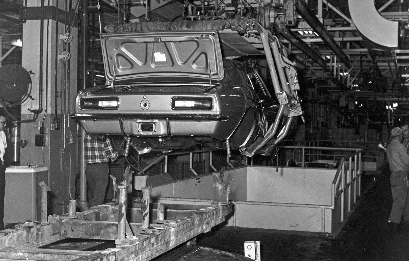
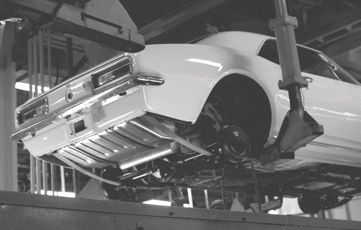
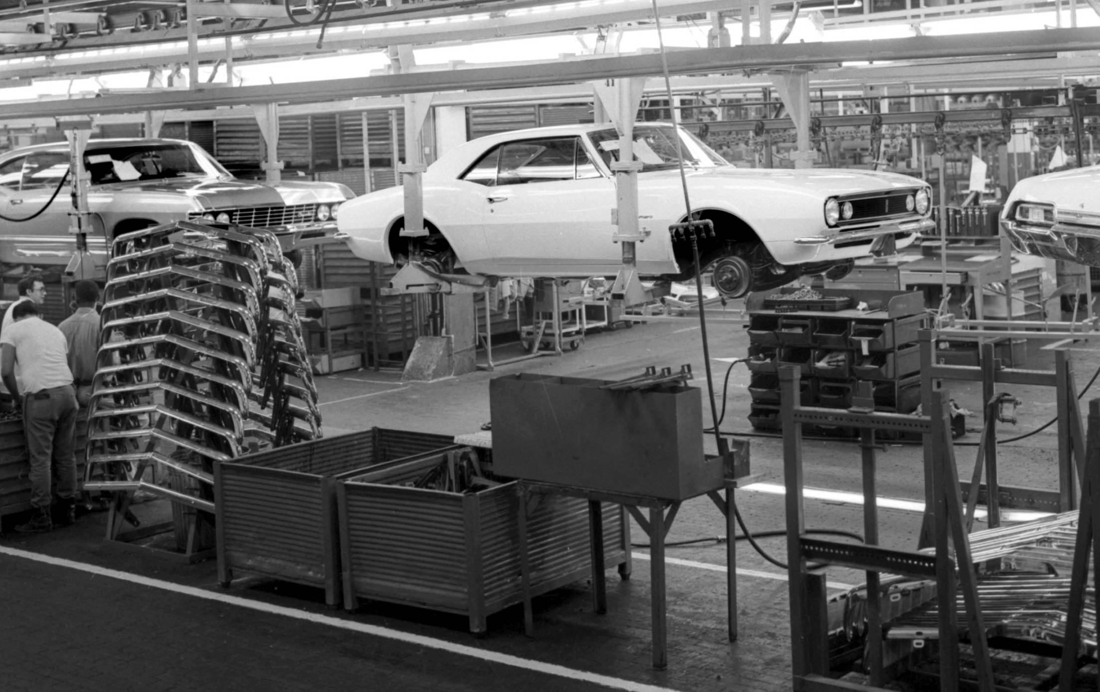
The most common body-to-chassis joining process was the "body drop", where the trimmed body was picked up off its body truck with an overhead "body drop tackle" device, which then "dropped" the body vertically on the chassis, which was being carried on a pedestal conveyor. The body mount bolts were then driven (4 on a partial-frame Camaro/Firebird "F" body, 10 on a full-frame "A" or "B" body), and the body/chassis was set down on its wheels on a flat-top Final Line conveyor. This process was employed at Norwood.
Plants with a history of building fully-unitized bodies installed the front sheet metal back on the Trim Line and used a "Towveyor" system to join the body and chassis. The body (including the front sheet metal) was in an overhead "clamshell" carrier six feet off the floor. The chassis was built-up and carried on a "Towveyor" device pulled by a conveyor chain in the floor that was synchronized with the overhead body conveyor. Each Towveyor had a hydraulic unit that raised the chassis up to the body so the body bolts and all other chassis-to-body attachments could be made. The Towveyor was then lowered and returned in a continuous loop to have another chassis assembled on it. This process was employed at Van Nuys, which built both partial-frame "F" bodies and full-frame "B" bodies on the same line.
As passenger car frames disappeared, fully unitized body construction became the norm and the front sheet metal was installed in the Body Shop. At that point, the Towveyor method became the process of choice for joining the chassis and the body.

|
|
|
Subsequent operations in the Final Line center pit were the same in both plants: the speedo cable was connected, fuel and brake line clips were secured to the underbody, the rest of the exhaust hangers were attached, the main fuel line was attached to the hose from the fuel tank, and the parking brake cables were secured and adjusted. Automatic shift linkage and clutch linkages were adjusted, the backdrive linkage was connected and adjusted, and the convertible floorpan brace was installed.
Up top, the steering column flange was connected to the rag joint, followed by securing the loosely-installed column to the dash and at the toe plate with its trim cover, manual floor shift levers, boots, and retainers were installed along with console trim plates. The master cylinder was pulled rearward and attached to the dash studs or the booster, and final wiring and plumbing connections were made.

|

|
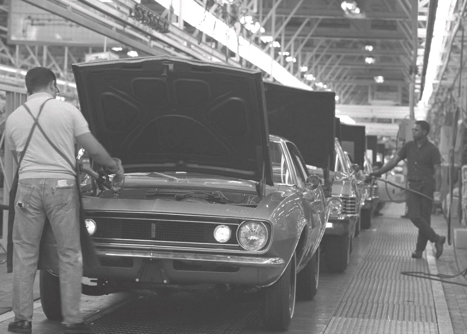
Four or five gallons of gas were pumped into the tank, the carburetor was primed by filling the float bowl through the vent tube, and the car was started for the first time; idle speed was adjusted, automatic transmissions were topped-off, the air cleaner was installed, and the car was ready for drive-off.
The Scheduling clerk had already produced the P-O-P from the Broadcast Copies picked up at the Engine and Chassis lines, the window sticker, car shipper, and final order copy had been produced, and these were placed in the glove box with the warranty folder and owner's manual while the window sticker was applied to the door glass. The car was then "de-papered" by removing all the extra Broadcast Copies, supplier labels, etc. that were taped all over the car as assembly information, and trashing them. Each car and its scheduled subassemblies picked up about twenty Broadcast Copies at it progressed through the Chevrolet assembly system, but it was strictly an internal plant information document and none were shipped with the car's paperwork package to the dealer, although many 1969 Van Nuys units had a Broadcast Copy glued to the top of the gas tank.
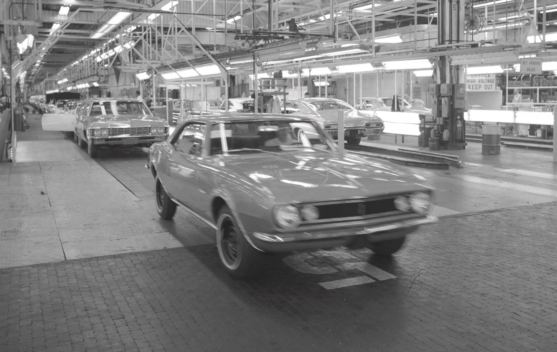
A team of inspectors gave the car a once-over, and a roll-tester drove the car off the end of the line into the toe-in machine. Here the driver used a fixture that rested on the window opening to hold the steering wheel level while the machine operator in the pit adjusted the tie rod sleeves until toe-in was in spec and tightened the tie rod sleeve clamps. The driver then returned the steering wheel fixture to the pedestal, and drove ahead onto the roll-test machine.
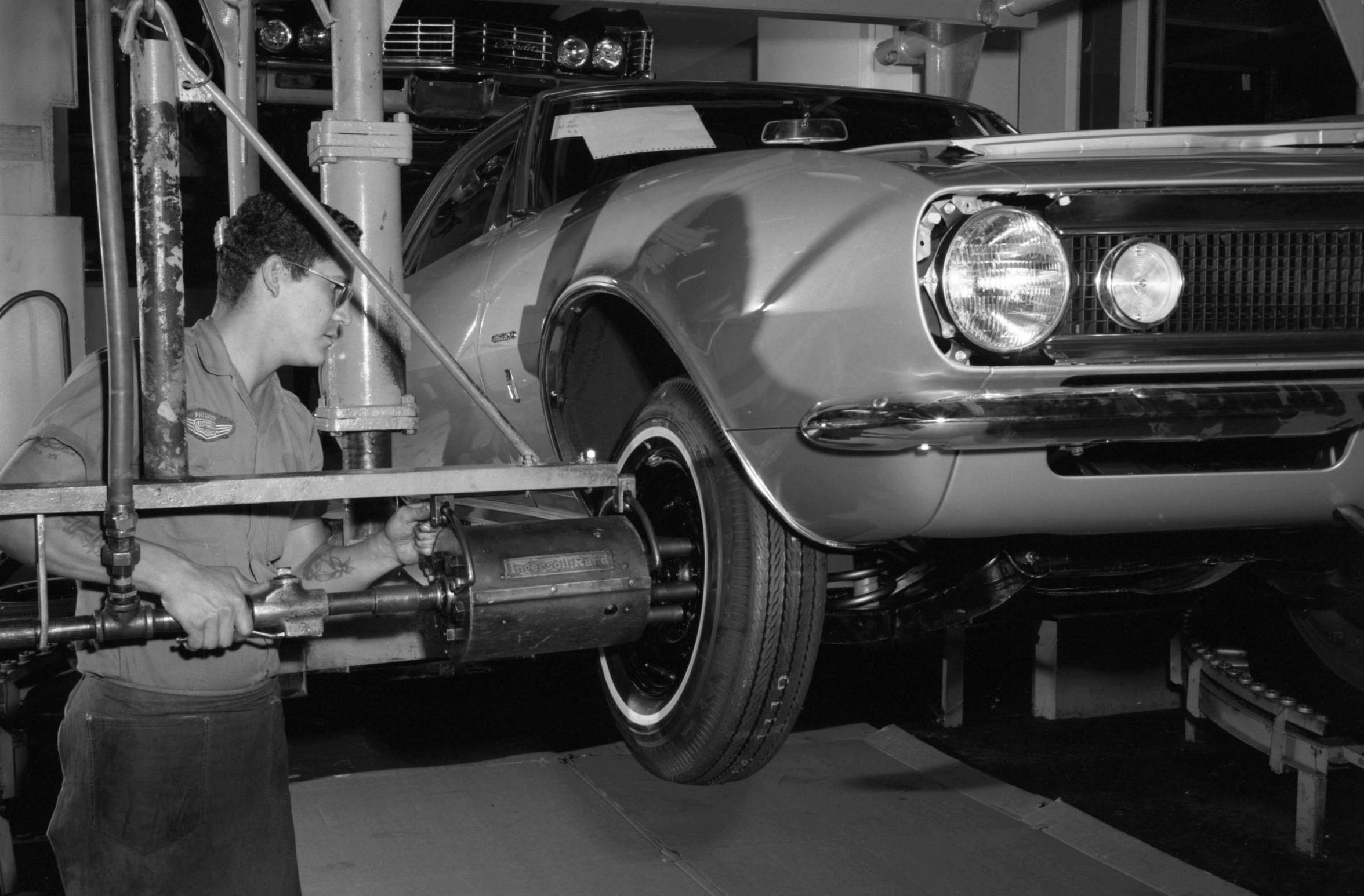
The roll-tester drove the car on the rollers at speeds up to 60 mph or so, checking mechanical operation, instruments, speedometer accuracy (a large master speedometer was suspended overhead in the driver's view), upshifts/downshifts, clutch, brakes, wipers, horn, turn signals, radio, acceleration, A/C operation, and listened for any unusual noises. One side of the rollers was smooth and round, and the other side were eccentric, to mimic driving the car on a rough road - the driver moved the car over to the rough side and listened for any squeaks or rattles, and when the rollers stopped, he drove the car ahead and parked it on another dual-strand flat-top conveyor, noted any discrepancies on the inspection ticket, and returned to pick up another car.

GM Photo")
|
The shipping line was another flat-top conveyor, which carried the now-finished car "out the door" to the shipping contractor; the car got one more once-over here, and all extraneous labels, stickers, and inspection tickets were removed. At the end of the line, the contractor drove the car away to his shipping yard adjacent to the plant where loads were made up for loading on haulaway trucks or rail cars to begin the journey to the ordering dealer.
Generally, cars to be delivered within several hundred miles of the plant left on haulaway trucks; those destined for dealers further away were shipped by rail, then unloaded at the nearest GM railhead to the dealer and transferred to haulaway trucks for final delivery.
Chrysler 1985-2001: Retired Plant Manager - Conner Avenue Assembly Plant (Viper & Prowler). Chief Engineer - Project Liberty. Chief Engineer - Advanced Process Development. Director - Advanced Manufacturing Engineering.
GM 1964-1985 (Chevrolet and GM Assembly Division): Production, Production Engineering, Vehicle Engineering, Product Promotion Engineering, Process Engineering, Pilot Operations, New Model Pre-Production & Launch.
BSME, Michigan State.
|
|


