This section allows you to view all posts made by this member. Note that you can only see posts made in areas you currently have access to.
Topics - Edgemontvillage
1
« on: April 23, 2024, 05:52:44 AM »
Friend is purchasing a 69 Pace Car project and is asking if the trim tag is original, would appreciate feedback. I plan to look at the car with him later this week so I don't have additional details just yet. 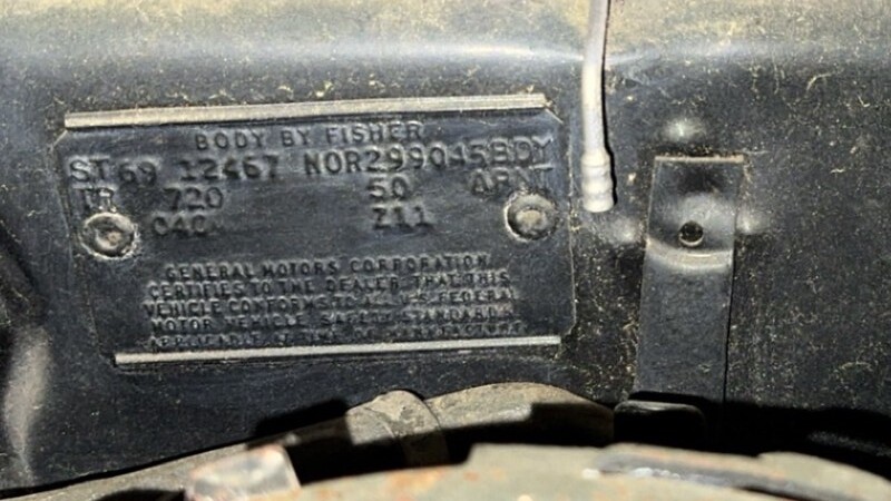
2
« on: May 30, 2022, 08:50:06 PM »
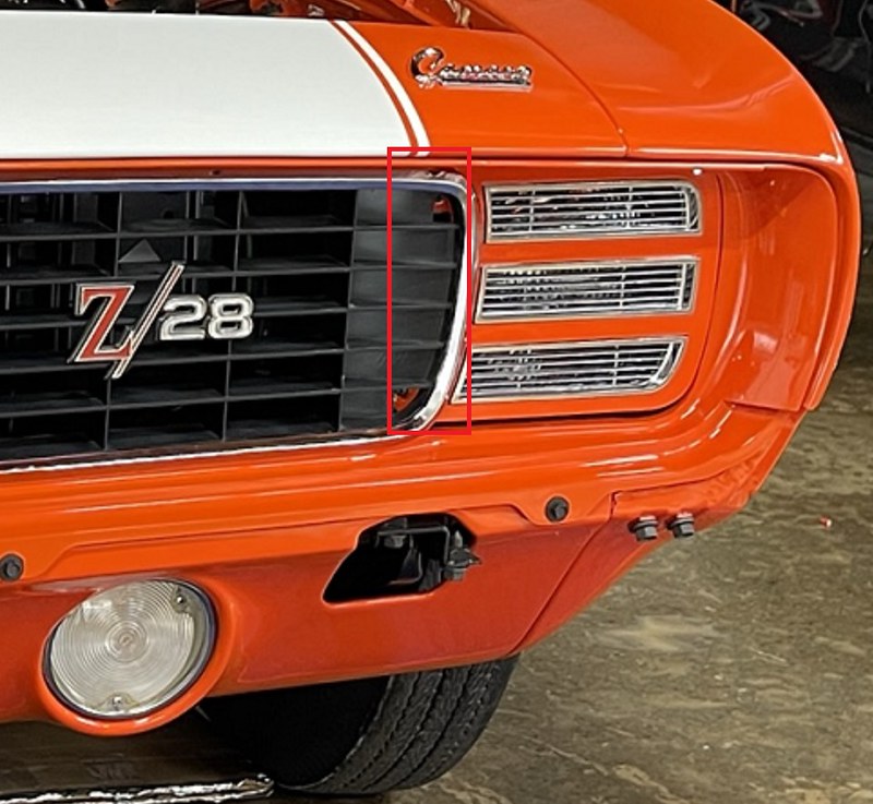
I'm fitting the RS headlight doors and grill on my 1969 RS Z project and a friend (..we'll call him Eddie M (enio45)) mentioned that on at least 2 Rally Sport equipped cars he's worked on, the inside corners of the headlight door covers where they are screwed to the backing plate, had been brush painted black to blend with the black plastic grill. If not painted black (or silver on black cars), the corners will show body color through the grill when the headlight doors are closed. Looking through my photo library and searching on-line I haven't been able to find an example of an original paint 69 Rally Sport optioned car (including Pace Cars) to confirm this blackout treatment. If you have an original paint Rally Sport optioned 69 would you please post if you have the door cover blackout. Thanks.
Inside Corners of Headlight Door Cover that would have received black out treatment.

Grill See-through showing (Hugger Orange) Body Color
4
« on: October 17, 2021, 03:17:24 PM »
I've got a couple of questions regarding Legends judging criteria for the Rally Sport option on a 69 Camaro. There are some inconsistencies I've seen on original, Norwood OH built RS equipped cars and I'd like to understand how these items are judged. If you've been through the judging process with a 69 RS optioned car please post here or send me a PM. Thanks.
5
« on: August 26, 2021, 04:54:50 PM »
Looking for the correct length of the thin wall radiator overflow hose. The AIM provides no details and I assume the hose length was the same for all Gen 1's however if not I'm looking for a 69 Z. Thanks.
6
« on: July 26, 2021, 09:17:29 PM »
I'm in the process of installing a new wiring harness kit from American Auto Wire (AAW) on my 1969 Camaro RS Z/28 project. Overall the engine harness from AAW is quite accurate however I have run into a few deviations from original that need correction including the terminal for the engine temperature sending unit with U17 console gauge option. On the 69 Z with console gauges the terminal was a bare brass friction fit slip-on type with no (plastic) connector however the AAW kit includes a ring style terminal that would require a nut to secure the terminal to the sending unit. AAW doesn't supply the correct terminal (although they did supply a console gauge harness) so I've been trying to locate one and the common 3.5mm bullet terminal is too small to fit over the sender post. Anyone have a good source for these connectors?


9
« on: April 09, 2021, 08:28:11 PM »
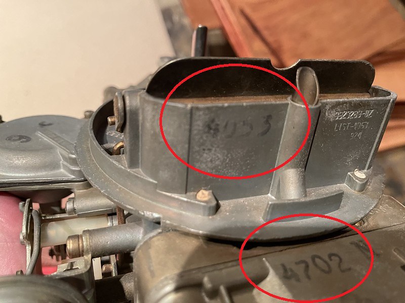
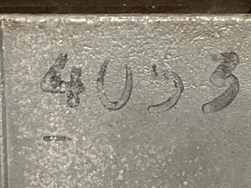
I'm trying to identify the font used for the carburetor ink stamps below. The photos are of an NOS 4053 carb I own dated 924 (4th week of Feb 1969) and I'd like to get ink stamps made so I can duplicate them for my project Z. For reference, the letters are 8mm or 5/16" high. Anyone recognize the font?
11
« on: March 18, 2021, 12:10:36 AM »
The positraction caution label was originally printed on non-adhesive backed, non-coated paper and applied to the underside of the trunk lid with glue. From what I've seen on Gen 1s where only glue residue remains where the label once was (often the case), the glue appears to have been applied in a cross or X pattern and rarely provided edge-to-edge coverage or full label adhesion. Its been suggested the glue was applied in multiple dabs however that's unlikely in high-volume production lines like Fisher's where economy of motion and effort is the standard. Based on the glue pattern in the photo below from my project, its also unlikely that a roller applicator was used but possibly a large sponge or mop-head style applicator or? The glue, I expect, would have been non water-based (due to recurring condensation on the underside of the trunk lid) and shows a semi-transparent off-white/yellow color (how much of this is age related?). I'd like to duplicate this glue and application technique for my project and would appreciate input on currently available glue products and applicators that would produce similar results to the original.
Positraction Caution Label

Glue Residue from the Positraction Caution label on my 69 2B Norwood Z.

12
« on: March 07, 2021, 05:19:46 AM »
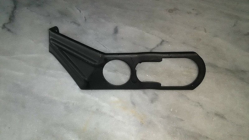
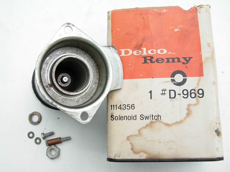
The smog / A.I.R. assembly was missing when I purchased my 1969 RS/Z project with the exception of the carrier bracket so I needed to locate suitable original parts. I sourced this rebuilt January 1969 dated smog pump some time ago however its functional and will need to be de-veined. The quality of the restoration is lacking, at least to my liking, so I searched for rebuild instructions on-line and couldn't find much. I thought I would create a thread on smog pump rebuilding for future CRG reference. There are threads on de-veining the internal pump-fan assembly however in order to do a comprehensive restoration the entire smog pump needs to be disassembled, the case restored and new bearings installed.


Dated 017 9 or January 17, 1969

Disassembly
The backing plate is secured by 4 bolts and once they are removed the plate can be carefully separated from the case. As the backing plate is cast iron and uses 2 locating pins it requires some effort to remove, care is needed to separate it from the aluminum case to avoid damage.

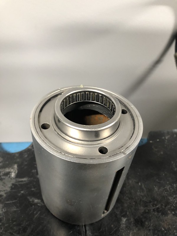
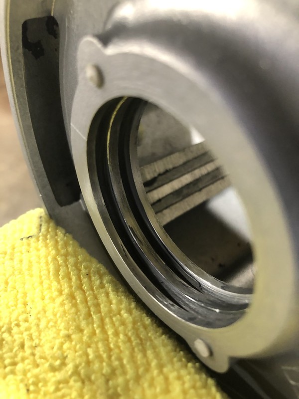
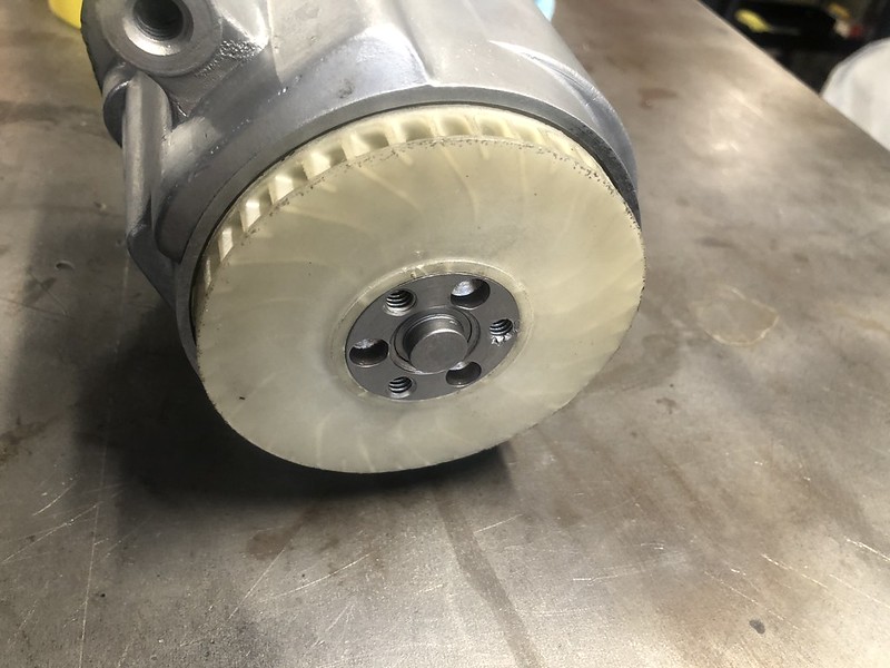
With the backing plate removed, inside the case is a steel drum with plastic or Bakelite fan blades that are loaded on, and rotate around, a center shaft attached to the backing plate as shown. The blades need to be removed and are easily broken up with a few blows from a chisel and hammer. This is the common de-veining process. The broken blades can then be shaken out of the case. At the end of each plastic fan blade is a (sharp) metal scraper blade that also needs to be removed. Have a close look inside the drum for any remaining plastic bits and pieces.
Case-back removed

Internal drum with fan blades

De-veined

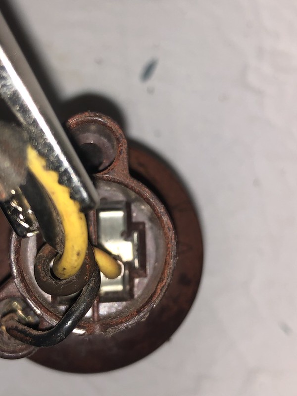
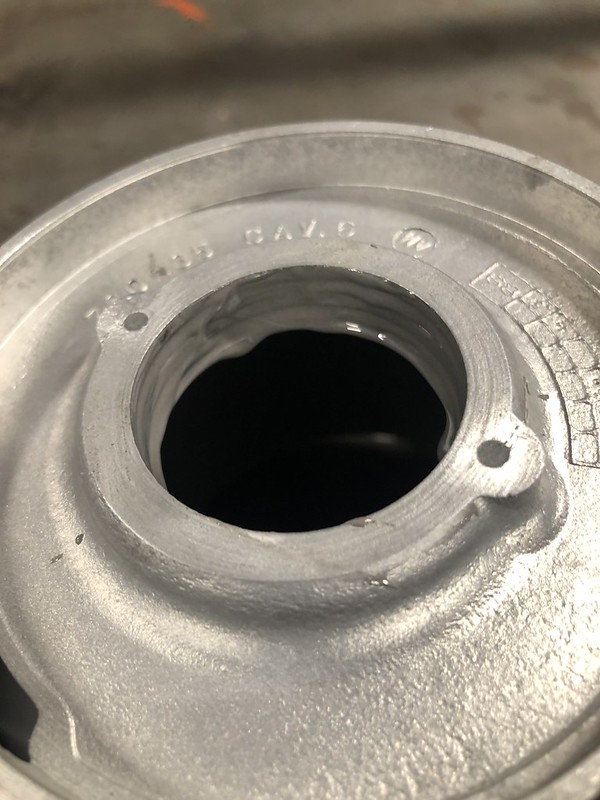
To remove the plastic cooling fan from the hub I used a plastic trim tool to access the back of the fan through a slot located in the top of the aluminum case. I rotated the fan 90 degrees tapped lightly and repeated until it was removed undamaged.
Plastic cooling fan

Slot in the top of the case where the trim tool can access the back of the fan

Tap the fan through the slot using the trim tool, rotating the fan occasionally until it separates from the hub, its a friction fit.

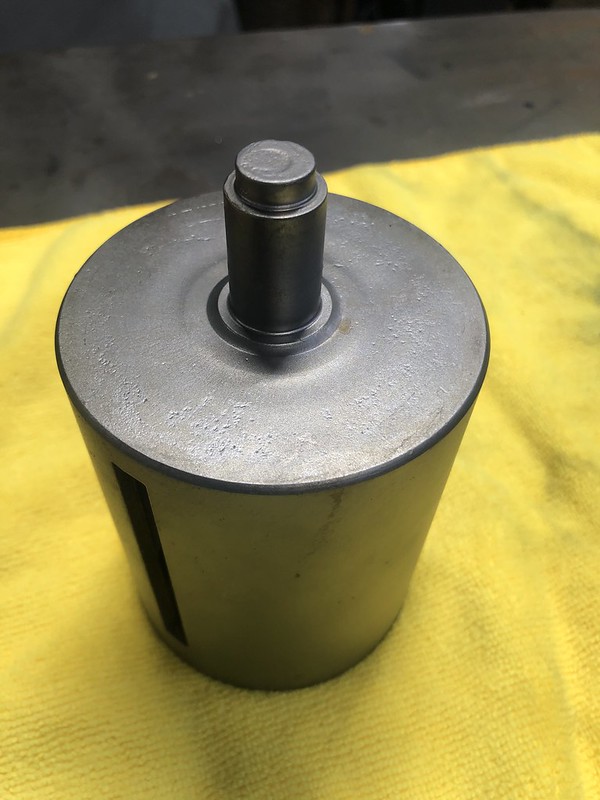
Once the plastic fan is removed the steel internal drum can be pressed out of the case via the extended tip of the drum (on the yellow graffiti mark). The fan hub will release from the tip as well.


There are 2 bearings in the smog pump, a needle bearing, style B248 1 1/2" ID x 1 7/8" OD x 1/2" width that is pressed into the access hole in the internal drum and another on the top or pulley end of the case, a sealed 6203LLBC3/EM radial ball bearing, 17 mm bore ID, 40 mm OD, 12 mm width.
The needle bearing is pressed out of the internal drum. Actually I pressed the bearing into the drum then fished it out with a pry tool. Easier than trying to pull it with a slide puller
Attempt to pull the needle bearing with a slide puller - not effective


Sealed radial bearing

At the top of the aluminum case is the sealed radial ball bearing that is retained by injected plastic. I was able to press this bearing out by supporting the bearing carrier on the top of the case then pressing the bushing out from the inside of the case. Care is needed as the case is aluminum and easily damaged. The injected plastic material has a low melting point so another (better) option is to heat the aluminum case around the bearing with a propane or MAPP gas torch before attempting to press it out. That will significantly ease the removal.

Disassembled pump following cleanup

Re-Assembly
First, press the cooling fan back onto the hub, this can be done with a rubber mallet. I find it easier with the fan face-down so the hub seats flush against the table surface. The fan is fragile so care is needed. Its a simple friction fit so no adhesive is required.


Next press the new needle bearing into the internal drum. As the drum is steel pressing the bearing in is straight forward. Once pressed in I packed the bearing with heavy duty wheel bearing grease.


Installing the a new radial sealed bearing into the case. First, I removed the original injection plastic with a Dremel grinding wheel then polished the mating surface with a Scotchbrite bit. This left two deep grooves.


The sealed bearing is semi-friction fit and requires a locking material to retain it in place. IMO this isn't a very good design, a bearing retainer ring like the one used for the main bearing in the alternator is easier to work with. I used J-B Weld epoxy that requires 15 hours curing time. I liberally filled the channels previously occupied by the injection plastic and pressed the new bearing in place then set the case aside for the epoxy to cure.

Injection channels loaded with J-B Weld
The new bearing loaded from the inside of the case and pressed in. Very little force was needed.


Now the wait for the J-B Weld to cure

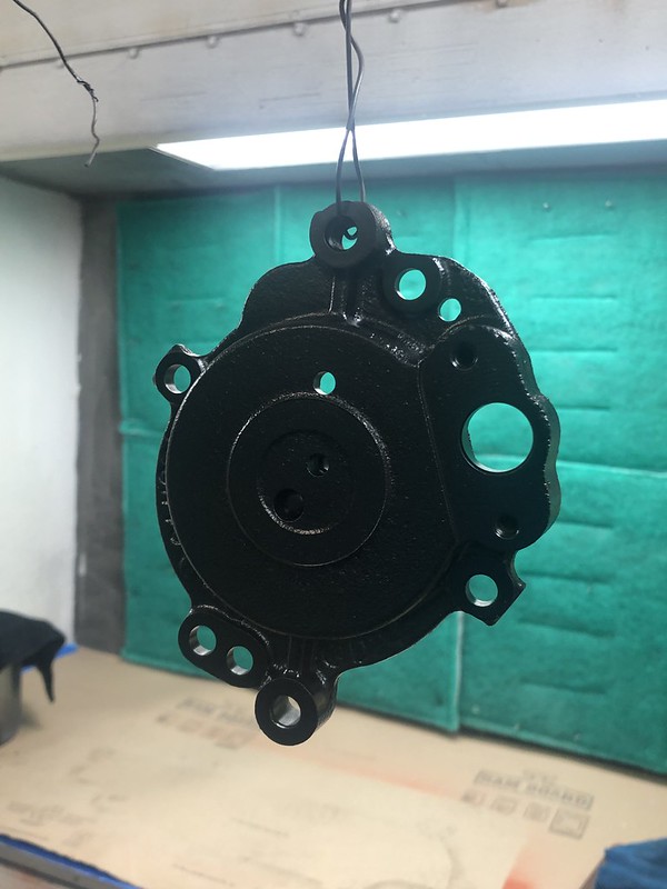
In the meantime a couple of small things to take care of, media blast and paint the backing plate (semi-gloss black) and re-plate the 4 bolts for the backing plate (clear zinc)


With the J-B Weld fully cured the next step is to press the internal drum tip onto the the sealed bearing. This is the most delicate step in the process as it stresses the bearing and the epoxy filler / adhesive. I supported the bearing edge and the bearing carrier surface of the case then pressed the drum tip through the center of the sealed bearing.

The fan hub is pressed onto the stem on the drum from the top of the case. The drum must be supported from the bottom and not allowed to "dangle" inside the case or the sealed bearing could be unseated.

The backing plate can now be reinstalled on the back of the case and secured with the newly re-plated bolts. Once the backing plate is secure the fan-hub should spin freely, if not the drum is likely binding on the back of the case and hasn't been pressed through the sealed bearing far enough. It will need to be adjusted.
Wheel bearing grease is added to the bearing contact surface.


Note the drum tip is fully extended through the fan hub.
The rebuilt smog pump with the pulley bolts and lock washers added

13
« on: December 18, 2020, 08:51:44 PM »
I'll be re-installing the parking brake assembly on my 69 RS/Z project soon and in preparation was reviewing pre-tear down photos of the (2) flange nuts where they attach the assembly to the firewall, to confirm their finish. I thought the finish was manganese (dark) phosphate, consistent with the flange nuts used to attach the brake booster to the firewall, however from the photo below it appears the finish is instead gold dichromate / gold zinc. Can anyone confirm this? 
14
« on: December 08, 2020, 11:25:40 PM »
The trunk lock retainer bracket was missing from my 1969 RS/Z (2B Norwood) project and I need to confirm the correct version. Here are photos of what may be the correct style, would appreciate input / confirmation: (photos from eBay)